
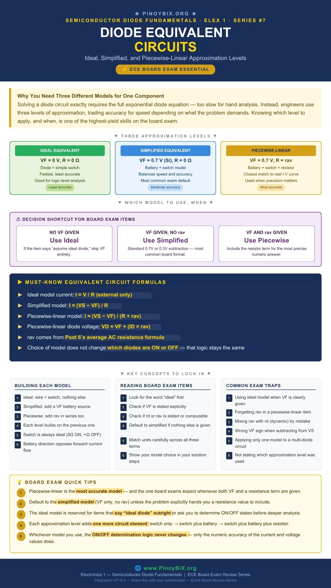
Solving a diode circuit exactly requires the full exponential diode equation — far too slow for hand analysis on a board exam. Instead, engineers use three levels of approximation, trading accuracy for speed depending on what a problem actually requires. This post ties together everything from this series into the diode equivalent circuits you will use for the rest of your electronics coursework: ideal, simplified, and piecewise-linear.
This is Part 7 of the Semiconductor Diode Fundamentals ECE Board Exam Reviewer Series on PinoyBIX.org. Part 6 covered diode resistance levels and temperature effects. This part uses that resistance knowledge directly, in the most accurate of the three approximation levels below. If you are reviewing for the ECE or EE board exam or currently enrolled in Electronics 1, save this page.
- ECE (Electronics Engineer) — Choosing and applying the correct approximation level is tested constantly, both directly and embedded inside larger rectifier, clipper, and regulator problems. Expect 3 to 5 items requiring you to identify which model a problem calls for and compute accordingly, often as the deciding factor between a correct and incorrect final answer.
- EE (Electrical Engineer) — Appears with moderate frequency, mostly testing the simplified model and basic ideal-versus-practical distinction rather than full piecewise-linear analysis.
Bottom line: ECE examinees must be fluent in all three models and know exactly when to apply each one. EE examinees need confident use of the simplified model.
Ideal Equivalent Circuit
The ideal model, introduced in Post 1, treats the diode as a plain switch: zero resistance when ON, infinite resistance when OFF, with no voltage drop. It is the fastest model and the least accurate.
![\[V_F = 0\text{ V}, \quad R = 0\ \Omega \quad \text{(ON state)}\]](https://pinoybix.org/wp-content/ql-cache/quicklatex.com-5bbbf196c869990bd86d10376a2c847c_l3.png "Rendered by QuickLaTeX.com")
![\[I = \dfrac{V}{R} \quad \text{(external resistance only)}\]](https://pinoybix.org/wp-content/ql-cache/quicklatex.com-1554470a074c70da6b06ce014bc8481d_l3.png "Rendered by QuickLaTeX.com")
Simplified Equivalent Circuit
The simplified model adds a battery representing the material’s threshold voltage  , while still treating the diode’s own resistance as zero once conducting. This is the most commonly used model on the board exam, and the default choice whenever a problem gives you but no resistance term.
![\[I = \dfrac{V_S - V_F}{R}\]](https://pinoybix.org/wp-content/ql-cache/quicklatex.com-28f6c7321e54381b072ba6169b64fc80_l3.png "Rendered by QuickLaTeX.com")
Piecewise-Linear Equivalent Circuit
The piecewise-linear model adds one more element: the diode’s own average AC resistance,  , in series with the battery and switch. This is the most accurate of the three models and the one board exams expect whenever both and a resistance value are provided.
![\[I = \dfrac{V_S - V_F}{R + r_{av}}\]](https://pinoybix.org/wp-content/ql-cache/quicklatex.com-bdeec14ab77679550727c463b8978995_l3.png "Rendered by QuickLaTeX.com")
![\[V_D = V_F + (I_D \times r_{av})\]](https://pinoybix.org/wp-content/ql-cache/quicklatex.com-d231d5cb51df90fe8bc02385a10e99ec_l3.png "Rendered by QuickLaTeX.com")
Which Model to Use, When
The choice of model does not change which diodes are ON or OFF — that logic, covered in Post 1 and Post 4, stays the same regardless of approximation level. The model choice only affects how precisely you calculate voltage and current once a diode is known to be conducting.
No given, or “ideal diode” stated: use the ideal model.
given, no resistance term: use the simplified model.
Both and (or enough data to compute it) given: use the piecewise-linear model.
Worked Problems — Board Exam Type Questions
The following 10 problems are representative of actual ECE and EE board exam questions on diode equivalent circuits. Work each problem by hand before reading the solution.
Problem 1 — ECE Board Exam Type
Using the ideal model, a diode is in series with  and
and  V, forward biased. Find the current.
Given: Ideal model, , V
Find: 
Solution:
Step 1: Under the ideal model, the conducting diode drops 0 V.
Step 2: 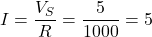 mA
mA
 mA
mA
Examiner note: This is the fastest possible calculation, but the least accurate — compare to Problem 2 using the same circuit values.
Problem 2 — ECE Board Exam Type
Repeat Problem 1 using the simplified model with a silicon diode ( V).
V).
Given: Simplified model, Si diode, , V
Find:
Solution:
Step 1: 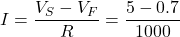
Step 2: 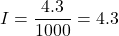 mA
mA
 mA
mA
Examiner note: This is a 14 percent difference from the ideal model result in Problem 1 — significant enough that board exams expect the simplified model whenever is given.
Problem 3 — ECE Board Exam Type
Repeat Problem 2 using the piecewise-linear model, given  for this diode.
Given: Piecewise-linear model, V, , , V
Find:
Solution:
Step 1: 
Step 2: 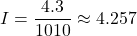 mA
mA
 mA
mA
Examiner note: The difference from the simplified model result (4.3 mA) is small here because is small relative to  , but this gap grows more significant in low-resistance circuits.
Problem 4 — ECE Board Exam Type
For Problem 3, find the actual voltage across the diode  using the piecewise-linear model.
Given: V, ,  mA
mA
Find:
Solution:
Step 1: Apply the piecewise-linear diode voltage formula.
![\[V_D = V_F + (I_D \times r_{av}) = 0.7 + (0.004257 \times 10)\]](https://pinoybix.org/wp-content/ql-cache/quicklatex.com-8934c632dba9ceb72f949b1dfc8ddbed_l3.png "Rendered by QuickLaTeX.com")
Step 2:  V
V
 V
V
Examiner note: Notice is slightly higher than the flat 0.7 V assumed in the simplified model — this small correction is exactly what the piecewise-linear model adds.
Problem 5 — ECE Board Exam Type
A board exam item states only “a silicon diode is in series with a 3 V source and a 470 Ω resistor.” No resistance term for the diode is given. Which model should be used?
Given: Si diode, implied, no given
Find: Correct model to use
Solution:
Step 1: The problem does not say “ideal,” so the ideal model is ruled out.
Step 2: No resistance term is given for the diode, so the piecewise-linear model cannot be applied either.
Examiner note: When in doubt and no explicit resistance value is provided for the diode, default to the simplified model with the standard material threshold voltage.
Problem 6 — ECE Board Exam Type
Two identical silicon diodes are in series, both forward biased, with  V and
V and  . Using the simplified model, find the current.
Given: Two Si diodes in series, simplified model, V,
Find:
Solution:
Step 1: Total diode drop:  V
V
Step 2:  mA
mA
 mA
mA
Examiner note: The simplified model extends cleanly to multiple diodes — just add each diode’s to the total drop before dividing by resistance.
Problem 7 — ECE Board Exam Type
Find the percent difference between the simplified model current from Problem 2 and the piecewise-linear model current from Problem 3.
Given:  mA,
mA,  mA
mA
Find: Percent difference
Solution:
Step 1: Compute the difference relative to the more accurate piecewise-linear result.
![\[\dfrac{4.3 - 4.257}{4.257} \times 100\% \approx 1.0\%\]](https://pinoybix.org/wp-content/ql-cache/quicklatex.com-016dd9a22d975c80d61eb1a15f63b490_l3.png "Rendered by QuickLaTeX.com")
Examiner note: Compare this small gap to the much larger 14 percent gap between ideal and simplified models in Problems 1 and 2 — the simplified-to-piecewise jump in accuracy is usually far smaller than the ideal-to-simplified jump.
Problem 8 — ECE Board Exam Type
A piecewise-linear model circuit has  V,
V,  , V, and produces a measured current of
  mA. Find .
Given: V, , V, mA
Find:
Solution:
Step 1: Rearrange the piecewise-linear formula to solve for  .
.
![\[R + r_{av} = \dfrac{V_S - V_F}{I} = \dfrac{10 - 0.7}{0.0178} \approx 522.5\ \Omega\]](https://pinoybix.org/wp-content/ql-cache/quicklatex.com-9946c608b844b8807311bcac791b7117_l3.png "Rendered by QuickLaTeX.com")
Step 2: Subtract the known resistance .
![\[r_{av} \approx 522.5 - 500 = 22.5\ \Omega\]](https://pinoybix.org/wp-content/ql-cache/quicklatex.com-0cd1f96aab2dae5694e722bd22ea60ae_l3.png "Rendered by QuickLaTeX.com")

Examiner note: Reverse-solving for a component value from a measured result is a common variation on straightforward calculation problems — the same formula, just rearranged.
Problem 9 — ECE Board Exam Type
Why does adding to the circuit always reduce the calculated current compared to the simplified model?
Given: Comparison between simplified and piecewise-linear models
Find: Explanation
Solution:
Step 1: The piecewise-linear model adds in series with the existing external resistance .
Step 2: A larger total resistance in the denominator of  always produces a smaller current than the simplified model’s
  .
.
adds to the total series resistance, increasing the denominator and reducing the current
Examiner note: This directional relationship is a fast way to sanity-check your answer — the piecewise-linear current should always be slightly lower than the simplified model current for the same circuit.
Problem 10 — EE Board Exam Type
An EE board item asks why an engineer would choose the simplified model over the piecewise-linear model even when data is available. What is the best justification?
Given: Design justification question
Find: Best answer
Solution:
Step 1: The piecewise-linear model is more accurate but requires more calculation steps and more known circuit data.
Step 2: When is small relative to the external resistance , the simplified model’s error is negligible, making the extra precision unnecessary for many practical estimates.
is small compared to
Examiner note: EE-level items often test this kind of practical trade-off reasoning rather than requiring full piecewise-linear computation.
Common Mistakes and Examiner Traps
| ❌ Mistake | ✅ Correction |
|---|---|
| Using the ideal model when is clearly given |
Default to the simplified model whenever a threshold voltage or material is stated, unless the problem explicitly says “ideal.” |
| Forgetting in a piecewise-linear item |
Add to the resistance in the denominator whenever both and (or enough data to find it) are provided. |
Confusing (average AC resistance) with  (dynamic resistance) (dynamic resistance) |
Use in the piecewise-linear equivalent circuit specifically — it comes from a broader swing on the curve, not a single tangent point. |
Wrong sign when subtracting from  |
Always subtract from , never the reverse, when the diode is forward biased and conducting. |
| Applying only one model to a multi-diode circuit inconsistently | Apply the same chosen model to every diode in the circuit, not a mix of ideal and practical assumptions. |
Board Exam Quick Tips
- Piecewise-linear is the most accurate model — use it whenever both and a resistance term are given.
- Default to the simplified model (VF only, no rav) unless the problem explicitly hands you a resistance value to include.
- The ideal model is reserved for items that say “ideal diode” outright or ask you to determine ON/OFF states before deeper analysis.
- Each approximation level adds one more circuit element: switch only → switch plus battery → switch plus battery plus resistor.
- Whichever model you use, the ON/OFF determination logic never changes — only the numeric accuracy of the current and voltage values does.
Frequently Asked Questions
Q1. Is the piecewise-linear model always the “correct” one to use?
Not necessarily correct in every case — it is the most accurate of the three, but the appropriate model depends on what data the problem actually provides. Using a model that requires data you don’t have is not possible in practice.
Q2. Why does the simplified model ignore the diode’s own resistance?
It is a deliberate simplification for speed. The diode’s forward resistance is usually small compared to typical circuit resistances, so ignoring it introduces only a small error in many practical cases.
Q3. Can the ideal model ever give the exact same answer as the simplified model?
Only if  V is somehow specified, which does not happen for real semiconductor materials. In practice, the ideal model always overestimates current compared to the simplified model.
Q4. Does the choice of model affect whether a diode is ON or OFF?
No. ON/OFF determination is based on bias direction and, in the practical models, whether the source voltage exceeds the threshold voltage. Once a diode is known to be ON, the model choice only affects the precision of the voltage and current values.
Q5. How does this topic connect to the rest of the Diode Applications series?
Every rectifier, clipper, clamper, and regulator circuit you will analyze uses one of these three models. Most board exam problems default to the simplified model unless stated otherwise, so mastering it is the highest-value skill from this post.
What Is Next
This series closes with one more post, covering the diode’s hidden capacitance, its switching speed limits, how to read a manufacturer’s spec sheet, and how to test a diode with real bench equipment.
→ Continue to Post 8 — Diode Capacitance, Switching Time, and Diode Testing
→ Back to the Semiconductor Diode Fundamentals Series Index
Published by PinoyBIX.org — Engineering Education for Every Filipino Student. Electronics · Mathematics · Board Exam Review · Free for Everyone.
Related Content




P inoyBIX educates thousands of reviewers and students a day in preparation for their board examinations. Also provides professionals with materials for their lectures and practice exams. Help me go forward with the same spirit.
“Will you subscribe today via YOUTUBE?”
TIRED OF ADS?
- Become Premium Member and experienced complete ads-free content browsing.
- Full Content Access to Premium Solutions Exclusive for Premium members
- Access to PINOYBIX FREEBIES folder
- Download Reviewers and Learning Materials Free
- Download Content: You can see download/print button at the bottom of each post.
PINOYBIX FREEBIES FOR PREMIUM MEMBERSHIP:
- CIVIL ENGINEERING REVIEWER
- CIVIL SERVICE EXAM REVIEWER
- CRIMINOLOGY REVIEWER
- ELECTRONICS ENGINEERING REVIEWER (ECE/ECT)
- ELECTRICAL ENGINEERING & RME REVIEWER
- FIRE OFFICER EXAMINATION REVIEWER
- LET REVIEWER
- MASTER PLUMBER REVIEWER
- MECHANICAL ENGINEERING REVIEWER
- NAPOLCOM REVIEWER
- Additional upload reviewers and learning materials are also FREE
FOR A LIMITED TIME
If you subscribe for PREMIUM today!
You will receive an additional 1 month of Premium Membership FREE.
For Bronze Membership an additional 2 months of Premium Membership FREE.
For Silver Membership an additional 3 months of Premium Membership FREE.
For Gold Membership an additional 5 months of Premium Membership FREE.
Join the PinoyBIX community.