
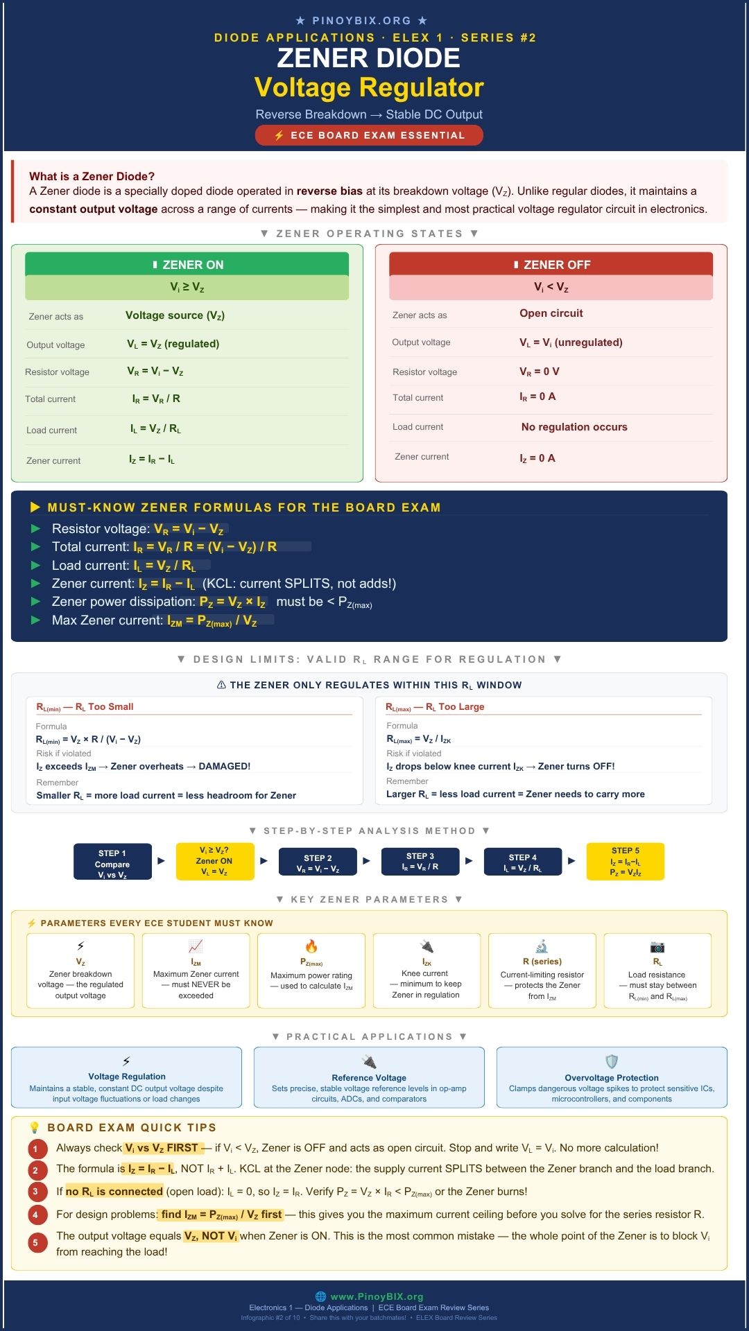
Every diode you have studied so far in this series avoids reverse breakdown at all costs. The zener diode is built to live there. It is designed to operate in reverse breakdown continuously, holding a nearly constant voltage across its terminals no matter how much the current through it changes within its rated range. That one property — a fixed voltage that holds steady while current swings — is what makes it the simplest voltage regulator you will study before moving into IC regulators.
This is Part 6 of the Diode Applications ECE Board Exam Reviewer Series on PinoyBIX.org. Part 4 covered diode clippers and Part 5 covered diode clampers. This part covers zener diode operation, the basic zener voltage regulator, line and load regulation, power rating checks, and the current limits that keep a zener regulator working correctly. This is one of the most heavily tested topics in the entire series — expect more items from this post than from any other post so far.
- ECE (Electronics Engineer) — Zener regulation is one of the most consistently tested topics in Electronics Engineering subjects. Expect 5 to 8 items covering series resistor design, current distribution (
 ,
,  ,
,  ), power rating checks, no-load and full-load extreme conditions, and line/load regulation computation. Very high-frequency topic — do not skip any part of this post.
 - EE (Electrical Engineer) — Appears in Electronics Engineering fundamentals, mostly as basic regulator circuit analysis and power dissipation checks. High frequency relative to other diode application topics.
Bottom line: ECE examinees must master full regulator design and analysis — series resistor sizing, current distribution at every load condition, and power rating verification. EE examinees must be confident computing  ,
,  ,
,  , and checking that zener power dissipation stays within rating. This is not a significant topic for ME, CE, ChE, GeE, MetE, MinE, or Naval Architecture boards.
What Makes a Zener Diode Different
A regular diode is destroyed if you push it into reverse breakdown and let current run away unchecked. A zener diode is manufactured with a controlled, sharp breakdown voltage and is meant to operate there continuously, as long as the current through it stays within its rated minimum and maximum. Below that breakdown region it behaves like an ordinary reverse-biased diode and blocks current almost entirely.
A zener diode regulates only while it is operating in reverse breakdown, between its knee current  (minimum current needed to sustain regulation) and its maximum rated current
  (set by its power rating). Outside that range, the diode either stops regulating (
 ) or overheats and fails (
 ).
).
The Basic Zener Voltage Regulator
The standard circuit places a series resistor  between the unregulated input voltage
  and a zener diode connected in parallel with the load
  . As long as the zener is in breakdown, the voltage across the load stays fixed at
  regardless of variations in or , within the diode’s rated current range.
![\[I_R = \dfrac{V_{in} - V_Z}{R}\]](https://pinoybix.org/wp-content/ql-cache/quicklatex.com-1989be456e6d2216667a3b2b49eecfa3_l3.png "Rendered by QuickLaTeX.com")
![\[I_L = \dfrac{V_Z}{R_L}\]](https://pinoybix.org/wp-content/ql-cache/quicklatex.com-e2587fab41e152dd20362a80e2a544b6_l3.png "Rendered by QuickLaTeX.com")
![\[I_Z = I_R - I_L\]](https://pinoybix.org/wp-content/ql-cache/quicklatex.com-8bf32532bf6870405c8ca9e05a201595_l3.png "Rendered by QuickLaTeX.com")
is the total current pulled from the source through the series resistor. It splits between the zener diode and the load. Whatever the load does not use, the zener absorbs — that self-adjustment is what holds constant.
Power Rating and the Zener’s Safe Operating Limit
The zener diode dissipates power continuously while conducting. If the design pushes too much current through it, it exceeds its rated power and fails. Every regulator design must check this before finalizing component values.
![\[P_Z = V_Z \times I_Z \leq P_{Z(max)}\]](https://pinoybix.org/wp-content/ql-cache/quicklatex.com-e0cfdfbfed1538436ce2ec1f4805843a_l3.png "Rendered by QuickLaTeX.com")
Rearranging gives the maximum allowable zener current for a given power rating:
![\[I_{ZM} = \dfrac{P_{Z(max)}}{V_Z}\]](https://pinoybix.org/wp-content/ql-cache/quicklatex.com-06cd90eefb0d5efa0d134f819a223dc6_l3.png "Rendered by QuickLaTeX.com")
The Two Extreme Conditions Every Design Must Survive
A regulator must keep the zener within its current limits across the worst-case combination of input voltage and load. Two conditions define the design boundary.
No-load ( , load removed): All of flows through the zener. This is the highest zener current the design will ever see — check
  here first.
Full-load (minimum , maximum ): The zener carries the least current. This is where regulation is most likely to fail — check  here.
here.
Line Regulation and Load Regulation
Two separate specifications describe how well a regulator holds its output steady, and board exams test both as distinct concepts.
![\[\text{Line Regulation} = \dfrac{\Delta V_Z}{\Delta V_{in}} \times 100\%\]](https://pinoybix.org/wp-content/ql-cache/quicklatex.com-2c1898bdbefb46aa753970bd04ec4cdf_l3.png "Rendered by QuickLaTeX.com")
![\[\text{Load Regulation} = \dfrac{V_{NL} - V_{FL}}{V_{FL}} \times 100\%\]](https://pinoybix.org/wp-content/ql-cache/quicklatex.com-63b72e84798181030a3d96bdb83dfdb7_l3.png "Rendered by QuickLaTeX.com")
Line regulation measures how much the output changes when the input source varies. Load regulation measures how much the output changes between no-load ( ) and full-load (
 ) conditions. Lower percentages mean better regulation in both cases.
Common Real-World Parts
The 1N47xx series (1N4728 through 1N4764) covers zener voltages from about 3.3 V to 100 V and is the standard general-purpose zener family used in regulator and reference circuits. Precision voltage reference ICs have largely replaced discrete zeners in critical applications, but the discrete zener regulator remains the standard teaching circuit and still appears in low-cost, low-current designs.
Where You Will Find This in Real Equipment
Zener regulators appear as simple fixed voltage references inside larger power supplies, as reverse-voltage and surge protection elements across sensitive IC inputs, and as bias voltage sources in transistor amplifier stages where a stable reference matters more than high current capability.
Worked Problems — Board Exam Type Questions
The following 10 problems are representative of actual ECE and EE board exam questions on zener diode voltage regulation. Work each problem by hand before reading the solution.
Problem 1 — ECE Board Exam Type
A zener regulator has  V,
V,  ,
,  V, and
  . Find , , and .
Given: V, , V,
Find: , ,
Solution:
Step 1: Find the total current through the series resistor.
![\[I_R = \dfrac{V_{in} - V_Z}{R} = \dfrac{20 - 10}{220} = 45.45 \text{ mA}\]](https://pinoybix.org/wp-content/ql-cache/quicklatex.com-4a583d9af18ff4c2b015e3f39e42cc41_l3.png "Rendered by QuickLaTeX.com")
Step 2: Find the load current.
![\[I_L = \dfrac{V_Z}{R_L} = \dfrac{10}{1000} = 10 \text{ mA}\]](https://pinoybix.org/wp-content/ql-cache/quicklatex.com-3e69bff9bafaa3bf3d6dcd04a5c1cc29_l3.png "Rendered by QuickLaTeX.com")
Step 3: Find the zener current by subtraction.
![\[I_Z = I_R - I_L = 45.45 - 10 = 35.45 \text{ mA}\]](https://pinoybix.org/wp-content/ql-cache/quicklatex.com-acc4e348e7ad5f12a4a8130a98606ef3_l3.png "Rendered by QuickLaTeX.com")
 mA;
mA;  mA;
mA;  mA
mA
Examiner note: Always compute first, then , then find by subtraction. Trying to compute directly without these two steps is where most arithmetic errors happen.
Problem 2 — ECE Board Exam Type
A zener diode has  V and
V and  W. Find .
Given: V, W
Find:
Solution:
Step 1: Apply the power-current relationship.
![\[I_{ZM} = \dfrac{P_{Z(max)}}{V_Z} = \dfrac{1}{12} = 83.3 \text{ mA}\]](https://pinoybix.org/wp-content/ql-cache/quicklatex.com-f5ec703a729e0b5fa203235eec18419c_l3.png "Rendered by QuickLaTeX.com")
 mA
mA
Examiner note: This is the ceiling value used to check the no-load condition. If the computed no-load exceeds this number, the design fails and the resistor value must be increased.
Problem 3 — ECE Board Exam Type
For the circuit in Problem 1, the load is removed (). If mA, does the zener survive the no-load condition?
Given: V, , V, removed, mA
Find: Whether the design is safe at no-load
Solution:
Step 1: With the load removed, all of flows through the zener.
![\[I_Z = I_R = \dfrac{V_{in} - V_Z}{R} = \dfrac{20 - 10}{220} = 45.45 \text{ mA}\]](https://pinoybix.org/wp-content/ql-cache/quicklatex.com-700f1648150e05f76de8409bb333355c_l3.png "Rendered by QuickLaTeX.com")
Step 2: Compare against .
![\[45.45 \text{ mA} < 83.3 \text{ mA} \Rightarrow \text{safe}\]](https://pinoybix.org/wp-content/ql-cache/quicklatex.com-7cc29d07fc78e64b4b210e19de04b92e_l3.png "Rendered by QuickLaTeX.com")
 mA is below the 83.3 mA maximum rating.
Examiner note: The no-load condition always produces the highest zener current for a given design. If a design fails at no-load, it fails as a whole — this is the first check to run, not the last.
Problem 4 — ECE Board Exam Type
A zener regulator must supply a load that draws current between 5 mA and 40 mA. If  mA and the series resistor produces
  mA, find at minimum load current and confirm whether regulation is maintained.
Given:  mA,
mA,  mA, mA, mA
Find: at full load (maximum load current) and regulation status
Solution:
Step 1: Full-load condition uses the maximum load current, since that pulls the most current away from the zener.
![\[I_Z = I_R - I_{L(max)} = 42 - 40 = 2 \text{ mA}\]](https://pinoybix.org/wp-content/ql-cache/quicklatex.com-b7205b70ced503dd40c9f31e2b4d46a5_l3.png "Rendered by QuickLaTeX.com")
Step 2: Compare against .
![\[2 \text{ mA} > 1 \text{ mA} \Rightarrow \text{regulation maintained}\]](https://pinoybix.org/wp-content/ql-cache/quicklatex.com-527278c1859d30052f942bd19cc73e92_l3.png "Rendered by QuickLaTeX.com")
 mA at full load; regulation is maintained since stays above .
Examiner note: Full-load is checked against , not . Students who apply the no-load check () to the full-load condition are checking the wrong limit for the wrong extreme.
Problem 5 — ECE Board Exam Type
Design a series resistor for a zener regulator with  V,
V,  V, and a desired zener current of
  mA at no load. Find .
Given: V, V, mA at no load ( , so
, so  )
)
Find:
Solution:
Step 1: At no load,  mA.
mA.
Step 2: Solve the series resistor formula for .
![\[R = \dfrac{V_{in} - V_Z}{I_R} = \dfrac{15 - 6.2}{0.020} = \dfrac{8.8}{0.020} = 440\ \Omega\]](https://pinoybix.org/wp-content/ql-cache/quicklatex.com-90715ecf87da79c176e82d8b1f076c16_l3.png "Rendered by QuickLaTeX.com")

Examiner note: Design problems run the standard formula backward. Identify what equals under the stated condition first — here, no load means directly — before solving for the unknown component.
Problem 6 — ECE Board Exam Type
A regulator shows  V at no load and
  V at full load. Find the load regulation percentage.
Given: V, V
Find: Load regulation (%)
Solution:
Step 1: Apply the load regulation formula.
![\[\text{Load Regulation} = \dfrac{V_{NL} - V_{FL}}{V_{FL}} \times 100\% = \dfrac{10.2 - 9.8}{9.8} \times 100\% = 4.08\%\]](https://pinoybix.org/wp-content/ql-cache/quicklatex.com-26743ca12ced0d30da64c26355af2a1b_l3.png "Rendered by QuickLaTeX.com")
Examiner note: The denominator is , the full-load value, not . Using the wrong denominator gives a different percentage and is a common exam trap.
Problem 7 — ECE Board Exam Type
A zener regulator’s output changes from 12.0 V to 12.3 V as changes from 18 V to 22 V. Find the line regulation.
Given:  V,
V,  V
V
Find: Line regulation (%)
Solution:
Step 1: Apply the line regulation formula.
![\[\text{Line Regulation} = \dfrac{\Delta V_Z}{\Delta V_{in}} \times 100\% = \dfrac{0.3}{4} \times 100\% = 7.5\%\]](https://pinoybix.org/wp-content/ql-cache/quicklatex.com-6784332db266c5f85c118f666aa7e965_l3.png "Rendered by QuickLaTeX.com")
Examiner note: Line regulation and load regulation are computed differently and answer different questions — one reacts to input voltage swings, the other reacts to load current swings. Do not use one formula in place of the other.
Problem 8 — ECE Board Exam Type
A zener regulator is designed with  ,
,  V,
V,  V, and
  . Find the power dissipated by the zener diode.
Given: , V, V,
Find: 
Solution:
Step 1: Find .
![\[I_R = \dfrac{24 - 9.1}{330} = \dfrac{14.9}{330} = 45.15 \text{ mA}\]](https://pinoybix.org/wp-content/ql-cache/quicklatex.com-9e55286ce3c87ec4ba6c745800f83085_l3.png "Rendered by QuickLaTeX.com")
Step 2: Find .
![\[I_L = \dfrac{9.1}{470} = 19.36 \text{ mA}\]](https://pinoybix.org/wp-content/ql-cache/quicklatex.com-be98196de2e596d8f2ba2b6195d354fd_l3.png "Rendered by QuickLaTeX.com")
Step 3: Find and compute power.
![\[I_Z = 45.15 - 19.36 = 25.79 \text{ mA}\]](https://pinoybix.org/wp-content/ql-cache/quicklatex.com-48daf03efc71e355a7061a06a458d579_l3.png "Rendered by QuickLaTeX.com")
![\[P_Z = V_Z \times I_Z = 9.1 \times 0.02579 = 0.235 \text{ W}\]](https://pinoybix.org/wp-content/ql-cache/quicklatex.com-43daf4b4d749d80c0310961f33c5bb19_l3.png "Rendered by QuickLaTeX.com")
 W
W
Examiner note: This problem chains three formulas in sequence. Missing or mis-ordering any one step throws off the final power figure — write out , , and explicitly rather than trying to combine steps mentally.
Problem 9 — ECE Board Exam Type
A zener regulator uses two 6.2 V zener diodes connected back-to-back in series, both in reverse breakdown for opposite half-cycles. What is this configuration commonly used for, and what is the approximate peak-to-peak output?
Given: Two 6.2 V zeners, back-to-back configuration
Find: Application and approximate output
Solution:
Step 1: In a back-to-back zener pair, one diode is in forward conduction while the other is in reverse breakdown, and they swap roles each half-cycle.
Step 2: This configuration is used as a symmetrical waveform clipper or AC voltage limiter, since each half-cycle is clamped near the zener voltage plus a forward diode drop.
![\[V_{o(peak)} \approx \pm(V_Z + V_D) = \pm(6.2 + 0.7) = \pm 6.9 \text{ V}\]](https://pinoybix.org/wp-content/ql-cache/quicklatex.com-895ef33aab694645e22716dd295af683_l3.png "Rendered by QuickLaTeX.com")
 V.
V.
Examiner note: This is a zener application question that borrows clipper concepts from Part 4 — the board exam frequently blends topics across posts in the same series like this.
Problem 10 — EE Board Exam Type
An EE board item asks why a series resistor is required in every zener voltage regulator circuit. What is the best explanation?
Given: General EE-level concept question
Find: Best explanation for the series resistor
Solution:
Step 1: A zener diode has almost no internal resistance once in breakdown — without a limiting element, current would rise uncontrolled.
Step 2: The series resistor sets and limits the current through the zener, protecting it from exceeding its maximum rated current.
Examiner note: EE-level items usually stop at this conceptual explanation rather than requiring full numeric regulator design. Understand the resistor’s protective role clearly.
Common Mistakes and Examiner Traps
These are the most consistent error patterns on ECE and EE board exam problems covering zener diode voltage regulation.
| ❌ Common Mistake | ✅ Correct Approach |
|---|---|
| Computing directly without first finding and separately. Skipping steps and guessing the split between load and zener. |
Always compute  first, then first, then  , then subtract to get , then subtract to get  . . |
| Checking the full-load condition against instead of . Applying the wrong current limit to the wrong extreme condition. |
No-load is checked against (maximum). Full-load is checked against (minimum). Match the condition to the correct limit. |
| Using as the denominator in the load regulation formula. Reversing which value belongs in the numerator and denominator. |
Load regulation is  . The full-load value is always the denominator. . The full-load value is always the denominator. |
| Forgetting to check the zener’s power rating after finding . Treating the current calculation as the final answer. |
Always compute  and compare it against and compare it against  before declaring a design acceptable. before declaring a design acceptable. |
| Assuming the zener regulates at any current value. Ignoring the knee current requirement entirely. | Regulation only holds between and . Below , the zener has left breakdown and no longer holds steady. |
Board Exam Quick Tips
- Always solve in this order: , then , then . Never attempt to compute in one step.
- No-load checks
 . Full-load checks
  . These are two different limits for two different extreme conditions — do not swap them.
 - Power check is mandatory, not optional. A correct current calculation with an unchecked power rating is an incomplete answer on design problems.
- Line regulation reacts to
 changes; load regulation reacts to
  changes. Match the given data to the correct formula before calculating.
 - Full-load denominator is always
 . Memorize this placement to avoid the most common regulation percentage error.
Frequently Asked Questions
Q1. What is the difference between and ?
is the knee current — the minimum current needed to keep the zener in breakdown and regulating. is the maximum rated current, set by the diode’s power rating, above which the zener overheats and fails.
Q2. Why does removing the load increase the current through the zener?
The series resistor current stays roughly the same regardless of the load, since it depends mainly on , , and . With no load current diverted through , all of has nowhere to go except through the zener, so rises to its maximum for that design.
Q3. Can a zener regulator handle large changes in load current?
Only within its designed range. As long as stays between and across the expected load current swing, regulation holds. Outside that range, either the zener stops regulating or it exceeds its power rating.
Q4. Is a zener regulator as efficient as an IC voltage regulator?
No. The series resistor wastes power continuously, and efficiency drops further at light loads since the zener absorbs most of the current itself. IC regulators are far more efficient and are used in most modern designs, but the zener regulator remains the standard teaching circuit for understanding basic voltage regulation.
Q5. Where are zener diodes used besides voltage regulation?
Zener diodes are used as fixed voltage references in comparator and bias circuits, as reverse-voltage transient protection across sensitive IC inputs, and in back-to-back pairs as simple AC waveform clippers or limiters.
What Is Next
Now that you can design and analyze a basic zener regulator across no-load and full-load conditions, the next post covers Voltage Multiplier Circuits — doublers, triplers, and quadruplers built from diodes and capacitors. Catch up first on Part 5 — Diode Clampers if you skipped it.
→ Continue to Part 7 — Voltage Multiplier Circuits
→ Back to the Diode Applications ECE Board Exam Reviewer Series Index
Published by PinoyBIX.org — Engineering Education for Every Filipino Student. Electronics · Mathematics · Board Exam Review · Free for Everyone.
Related Content



P inoyBIX educates thousands of reviewers and students a day in preparation for their board examinations. Also provides professionals with materials for their lectures and practice exams. Help me go forward with the same spirit.
“Will you subscribe today via YOUTUBE?”
TIRED OF ADS?
- Become Premium Member and experienced complete ads-free content browsing.
- Full Content Access to Premium Solutions Exclusive for Premium members
- Access to PINOYBIX FREEBIES folder
- Download Reviewers and Learning Materials Free
- Download Content: You can see download/print button at the bottom of each post.
PINOYBIX FREEBIES FOR PREMIUM MEMBERSHIP:
- CIVIL ENGINEERING REVIEWER
- CIVIL SERVICE EXAM REVIEWER
- CRIMINOLOGY REVIEWER
- ELECTRONICS ENGINEERING REVIEWER (ECE/ECT)
- ELECTRICAL ENGINEERING & RME REVIEWER
- FIRE OFFICER EXAMINATION REVIEWER
- LET REVIEWER
- MASTER PLUMBER REVIEWER
- MECHANICAL ENGINEERING REVIEWER
- NAPOLCOM REVIEWER
- Additional upload reviewers and learning materials are also FREE
FOR A LIMITED TIME
If you subscribe for PREMIUM today!
You will receive an additional 1 month of Premium Membership FREE.
For Bronze Membership an additional 2 months of Premium Membership FREE.
For Silver Membership an additional 3 months of Premium Membership FREE.
For Gold Membership an additional 5 months of Premium Membership FREE.
Join the PinoyBIX community.