

This is the summary notes of the important terms and concepts in Chapter 22 of the book "Electronic Communications System" by Wayne Tomasi. The notes are properly synchronized and concise for much better understanding of the book. Make sure to familiarize this review notes to increase the chance of passing the ECE Board Exam.
CHAPTER 22 |
FUNDAMENTAL CONCEPTS OF DATA COMMUNICATIONS |
Items |
Definitions |
Terms |
1 |
Often used to represent characters and symbols such as letters, digits and punctuation marks. Another terms: · character codes · character sets · symbol codes · character languages |
Data Communications Codes |
2 |
Sometimes called the Telex Code, was the first fixed length character developed for machines rather than for people. |
Baudot Code |
3 |
A French postal engineer who developed the baudot code in 1875 and named after Emile Baudot, an early pioneer in telegraph printing. |
Thomas Murray |
4 |
Fixed-length source code. |
Fixed Length Block Code |
5 |
Stands for United States of America Standard Code for Information Exchange, better known as ASCII-63. |
USASCII |
6 |
The standard character set for source coding the alphanumeric character set that humans understand but computers do not (computers only understand 1s and 0s). It is a seven bit fixed-length character set. |
ASCII |
7 |
Fixed-length source code. |
Fixed Length Block Code |
8 |
Extended binary coded decimal interchange-code, an eight bit fixed length character developed in 1962 by International Business Machines Corporation. |
EBCDIC |
9 |
Omnipresent block and white striped stickers that seem to appear or virtually every consumer item in the US and most of the rest of the world. |
Bar Codes |
10 |
It has spaces or gaps between characters. Each character is independent of every other character. |
Discrete Code |
11 |
It does not include spaces between characters. An example is Universal Product Code. |
Continuous Code |
12 |
It stores data in two dimensions in contrasts with conventional linear bar codes which stores data along only one axis. |
2D code |
13 |
It uses an alphanumeric code similar to ASCII code. It contains 9 vertical elements (5 bars & 4 spaces). It consists of 36 unique codes representing the 10 digits and 26 uppercase letters. Other Names: · Code 3 of 9 · 3 of 9 code |
Code-39 |
14 |
A continuous code since there are no interchangeable spaces. Each UPC label contains a 12-digit number. |
Universal Product Code |
15 |
It consists of a 101 (bar-soace-bar) sequence, which is used to frame the 12 digit UPC number. |
Start & Stop Guard Pattern |
16 |
It separates the left and right halves of the label and consists of two long bars in the center of the label. |
Center Guard Frame |
17 |
Caused by electrical interference from natural sources Classification of Data Com Errors: · single bit · multiple bit · burst Categories of Error Control : |
Transmission Errors |
18 |
Errors with only one bit within a given a given string is in error. |
Single Bit Errors |
19 |
Errors with two or more non-consecutive bits within a message. |
Multiple-bit error |
20 |
Errors when to or more consecutive bits within a given data string are in error. It can affect one or more characters within a message. |
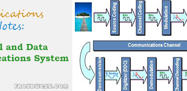
Burst Error |
21 |
The theoretical (Mathematical) expectation of the rate at which errors will occur. |
Probability of Error |
22 |
The actual historical record of a system’s error performance. |
Bit-Error Rate |
23 |
The process of monitoring data transmission and deter mining when errors have occurred. It neither correct errors nor identify which bits are in error-they only indicate when an error has occurred. |
Error Detection |
24 |
Adding of bits for the sole purpose of detecting errors. Types of redundancy checks: · vertical redundancy checking, · checksum, · |
Redundancy Checking |
25 |
A form of error detection by duplicating each data unit for the purpose of detecting errors. |
Redundancy |
26 |
An error detection bit. |
Parity |
27 |
The simplest error-detection scheme and is generally referred to as character parity. |
Vertical Redundancy Checking (VRC) |
28 |
An error detection bit in each character. |
Parity Bit |
29 |
The parity bit which is always a 1. |
Marking Parity |
30 |
The parity bit which is not sent or checked. |
Ignored Parity |
31 |
Form of redundancy error checking where each character has a numerical value assigned to it. |
Checksum |
32 |
A redundancy error detection scheme that uses parity to determine if a transmission error has occurred with n a message. |
Longitudinal Redundancy Checking (LRC) |
33 |
An error occurred within a message. |
Message Parity |
34 |
The group pf characters that comprise a message. |
Block or Frame of Data |
35 |
The bit sequence for the LRC. |
Block Check Sequence (BCS) or Frame Check Sequence (FCS) |
36 |
A convolution coding scheme that is most reliable redundancy checking technique for error detection. Almost 99.999% of all transmission errors are detected |
Cyclic Redundancy Checking |
37 |
Types of Error Messages. |
Lost Message Damaged Message |
38 |
One that never arrives at the destination or one that is damaged to the extent that it is unrecognizable. |
Lost message |
39 |
One that is recognized at the destination but contains one or more transmission errors. |
Damaged Message |
40 |
It includes enough redundant information with each transmitted message to enable the receiver to determine when an error has occurred. Examples: · Parity bits · block and frame check characters · cyclic redundancy characters |
Error-Detecting Codes |
41 |
It includes sufficient extraneous information along with each message to enable the receiver to determine hen an error has occurred and which bits is in error. Two primary methods for error correction: · Retransmission · |
Error-correcting Codes |
42 |
When a receive station requests the transmit station to resend a message when the message is received in error. |
Retransmission |
43 |
A two-way radio term which automatically a retransmission f the entire message. Types of ARQ: · Discrete · |
Automatic Repeat Request (ARQ) or Automatic Retransmission Request |
44 |
The recipient of data sends a short message back to the sender acknowledging receipt of the last transmission. Types of acknowledgements: · Positive · |
Acknowledgement |
45 |
A receive station becomes the transmit station such as when acknowledgments are sent or when retransmission are sent in response to a negative acknowledgment. |
Line Turnarounds |
46 |
It uses acknowledgments to indicate the successful or unsuccessful reception of data. |
Discrete ARQ |
47 |
It can be used when messages are divided into smaller lock or frames that are sequentially numbered and transmitted in succession, without waiting for acknowledgments between blocks. |
Continuous ARQ |
48 |
The sending station does not receive an acknowledgment after a predetermined length of time. |
Retransmission Time-Out |
49 |
The destination station asynchronously requests the retransmission of specific frame of data and still be able to reconstruct the entire message once all frames have been successfully transported through the system. |
Selective Repeat |
50 |
The error-correction scheme that detects and corrects transmission errors when they are received without requiring a retransmission. |
Forward Error Correction (FEC) |
51 |
A mathematician, who was an early pioneer in the development of error-detection and correction procedures, developed the Hamming Code while working at Bell Telephone Laboratories. |
Richard W. Hamming |
52 |
An error-correcting code used for correcting transmission errors in synchronous data streams. It requires the addition of overhead to the message, consequently increasing the length of a transmission. |
Hamming Code |
53 |
Inserted into a character at random locations. |
Hamming Bits |
54 |
The combination of the data bits and the hamming bits. |
Hamming Code |
55 |
It means to harmonize, coincide, or agree in time. |
Synchronize |
56 |
Involves identifying the beginning and end of a character with in a message. |
Character Synchronization |
57 |
Its literal meaning is “without synchronism”. In Data Com, it means “without a specific time reference” |
Asynchronous |
58 |
Asynchronous communications is called as such because each data character is framed between start and stop bits. |
Start-stop Transmission |
59 |
A condition when the transmit and receive clocks are substantially different. |
Clock Slippage |
60 |
It occurs when the transmit clock is substantially lower than the receive clock. |
Under slipping |
61 |
Occurs when the transmit clock is substantially higher than the receiver clock. |
Overslipping |
62 |
It involves transporting serial data at relatively high speeds in groups pf characters. |
Node |
63 |
Interconnects digital computer equipment. |
Synchronous Data |
64 |
Plain old Telephone system |
POTS |
65 |
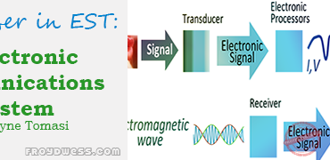
It is comprised of three basic elements: · transmitter (source) · transmission path (data channel) · receiver (destination) 3 fundamental components of endpoints: · data terminal equipment · data communications equipment · serial interface |
Data Communications System |
66 |
It can be virtually any binary digital device that generates transmits, receives, or interprets data messages. It is where information originates or terminates. |
Data Terminal Equipment (DTE) |
67 |
Devices used to input, output and display information such as keyboards, printers and monitors |
Terminal |
68 |
Basically a modern-day terminal with enhance computing capabilities |
Client |
69 |
High-powered, high capacity mainframe computers that support terminals. |
Hosts |
70 |
It functions as modern-day host. |
Servers |
71 |
A general term use to describe equipment that interfaces data terminal equipment to a transmission channel, such as a digital T1 carrier or an analog telephone circuit. It is a signal conversion device, as it converts signals from a DTE to a form more suitable to be transported over transmission channel. Types of DCE: · channel service units (CSUs) · Digital service units (DSUs) · data modems |
Data Communications Equipment (DCE) |
72 |
Another term for DCE. |
Data Circuit-terminating Equipment (DCTE) |
73 |
A DCE used to interface a DTE to an analog telephone circuit commonly called POTS. |
Data Modem |
74 |
It controls data flow between several terminal devices and the data communications channel. |
Cluster Controller |
75 |
Line control units at secondary stations. |
Station Controllers (STACOs) |
76 |
Universal Asynchronous Receiver/transmitter it is designed for asynchronous data transmission. |
UART |
77 |
A special purpose UART chip manufactured by Motorola. |
Asynchronous Communications Interface Adapter (ACIA) |
78 |
It means that an asynchronous data format is used and no clocking information transferred between the DTE and the DCE. |
Asynchronous Data Transmission |
79 |
An n-bit data register that keeps track of the status of the UART’s transmits and receive buffer registers. |
Status Word |
80 |
Transmit shift register has completed transmission of data character. |
Transmit Buffer Empty (TBMT) |
81 |
Set when a received character has a parity error in it. |
Receive Parity Error (RPE) |
82 |
Set when a character is received without any or with improper number of stop bits. |
Receive Framing Error (RFE) |
83 |
Set when a character in the receive buffer register is written over by another receive character. |
Receiver Overrun (ROR) |
84 |
A data character has been received and loaded into the receive data register. |
Receive Data Available (RDA) |
85 |
The difference in time between the beginning of a start bit and when it is detected. |
Detection Error |
86 |
It is used for synchronous transmission of data between a DTE and a DCE. Functions of USRT: · Serial to parallel and parallel to serial data conversions · Error detection by inserting parity bits in the transmitter and checking parity bits in the receiver. · Insert and detect unique data synchronization (SYN) characters · Formatting data in the transmitter and receiver. · Provide transmit and receive status information to the CPU. · Voltage-level conversion between the DTE and the serial interface and vice versa. · Provide a means of achieving bit and character synchronization. |
Universal Synchronous Receiver/transmitter (USRT) |
87 |
It should provide the ff: · A specific range of voltages for transmit and receive signal levels · Limitations for the electrical parameters of the transmission line. · Standard cable and cable connectors · Functional description of each signal on the interface. |
Serial Interface |
88 |
In 1962, standardized the interface equipment between data terminal equipment and data communications equipment. |
Electronics Industries Association (EIA) |
89 |
It means “Recommended Standards” |
RS |
90 |
The official name of the RS-232 interface. |
Interface Between Data Terminal Equipment and Data Communications Equipment Employing Data Communications Equipment Employing Serial Binary Interchange |
91 |
In, 1969, the third revision which was published and remained the industrial standard until 1987. |
RS-232C |
92 |
Sometimes referred to as the EIZ-232 standard Versions D and E of the RS-232 standard changed some of the pin designations. |
RS-232D |
93 |
It is a sheath containing 25 wires with a DB25P-compatible male connector (plug) on one end and a DB25S-compatible female connector (receptacle) on the other end. Two full-duplex channels: · Primary data-actual information · secondary data-diagnostic information and handshaking signals |
Star Topology |
94 |
It is designed for transporting asynchronous data between a DTE and a DCE or between DTEs. |
9-pin Version of RS-232 |
95 |
It is designed for transporting either synchronous or asynchronous data between a DTE and a DCE. |
25 pin Version |
96 |
It is designed exclusively for dial-up telephone. It is used for transporting asynchronous data between a DTE and a DCE when the DCE is connected directly to a standard two-wire telephone line attached to the public switched telephone network. |
EIA-561 |
97 |
It converts the internal voltage levels from the DTE and DCE to RS-232 values. |
Voltage-Leveling Circuits |
98 |
A voltage leveler wherein its output signals onto the cable. |
Driver |
99 |
It accepts signals from the cable. |
Terminator |
100 |
Protective ground, frame ground, or chassis ground. |
FUNCTIONS OF RS-232 PINS Pin 1 |
101 |
Transmit data or send data. |
Pin 2 |
102 |
Receive data (RD or RxD). |
Pin 3 |
103 |
Request to send (RS or RTS) |
Pin 4 |
104 |
Clear to send.(CS or CTS) |
Pin 5 |
105 |
Data set ready or modem ready.(DSR or MR) |
Pin 6 |
106 |
Signal ground or reference ground. |
Pin 7 |
107 |
Unassigned and non-EIA specified often held at +12V |
Pin 8 |
108 |
Receive line signal detect, carrier detect or data carrier detect (RLSD, CD or DCD) |
Pin 9 |
109 |
Unassigned and often held at -12 Vdc for test purposes |
Pin 10 |
110 |
Secondary receive line signal detect, secondary carrier detect or secondary data carrier detect (SRLSD, SCD, or SDCD) |
Pin 12 |
111 |
Secondary clear to send. |
Pin 13 |
112 |
Secondary transmit data or secondary send data |
Pin 14 |
113 |
Transmission signal element timing or serial Clock transmit. |
Pin 15 |
114 |
Secondary received data |
Pin 16 |
115 |
Receiver signal element timing or serial clock receive |
Pin 17 |
116 |
Unassigned is used for local loopback signal |
Pin 18 |
117 |
Secondary request to send |
Pin 19 |
118 |
Data terminal ready. |
Pin 20 |
119 |
Signal quality detector. |
Pin 21 |
120 |
Ring indicator (RI) |
Pin 22 |
121 |
Data signal rate selector (DSRS) |
Pin 23 |
122 |
Transmit signal element timing or serial clock transmit-DTE |
Pin 24 |
123 |
Unassigned. It is sometimes used as a control signal from the DCE to the DTE to indicate that the DCE is in either the remote or local loop back mode. |
Pin 25 |
124 |
It specifies a 37-pin primary connector DB37 and a 9 pin secondary connector DB9 for a total of 46 pins which provides more functions, faster data transmission rates and spans greater distances than the RS-232. Primary goals of RS-449: · Compatibility with the RS-232 interface standard · Replace the set of circuit names and mnemonics · Provide separate cables and connectors · Reduce crosstalk · offer higher data transmission · longer distances over twisted pair cables · loopback capable · improve performance and reliability specify a standard connector Two categories: · Category I · Category II |
RS-449 Serial Interface |
125 |
Used by the DTE to request a local loopback from the DCE. |
10 CIRCUITS IN RS-449 1.Local Loopback |
126 |
Used by the DTE to request a remote loopback from the distant DCE. |
2.Remote Loopback |
127 |
Allows the DTE to select the DCE’s transmit and receive frequencies. |
3. Select frequency |
128 |
Used by DTE to signal the DCE that a test is in progress. |
4.Test Mode |
129 |
Common return wire for unbalanced signals propagating from the DCE to the DTE |
5. Receive Common |
130 |
Used by the DTE to signal the DCE whether it is operational |
6. Terminal in Service |
131 |
Used by the DTE to request that the DCE switched to standby equipment. |
7. Select Standby |
132 |
Used with a modem at the primary location of a multipoint data circuit. |
8. New Signal |
133 |
It was intended to operate at data rates between 20 kbps and 2 Mbps using the same DB25 connector |
RS-530 Serial Interface |
134 |
It is used to interface computers, computer networks to analog transmission media Alternate names: · datasets · · |
Data Communications Modem |
135 |
A contraction derived from the words Modulator and Demodulator. Primary Block of a Modem: · Serial interface Circuit · Modulator Circuit · Bandpass filter and equalizer circuit · telco interface circuit · demodulator circuit · carrier and clock generation circuit |
Modem |
136 |
Data communications modems designed to operate over the limited bandwidth of the PSTN. |
Voice-band Modem |
137 |
It is able of transporting higher bit rates. |
Broadband Modem |
138 |
Digital to analog converter. |
DAC |
139 |
Analog to digital converter. |
ADC |
140 |
It is a rate of change of signals on the transmission medium after encoding and modulation have occurred |
Baud |
141 |
Refers to the rate of change of a digital information signal. |
Bit Rate |
142 |
It is classified as low-speed voice-band modems. |
Asynchronous Modems |
143 |
Synchronous data transported by asynchronous modems. |
Isochronous Transmission |
144 |
It uses PSK or quadrature amplitude modulation to transport data. |
Synchronous Modems |
145 |
A special, internally generated bit pattern in transmit modem. |
Training Sequence |
146 |
Located in the transmit section of a modem and provide pre-equalization |
Compromise Equalizers |
147 |
Located in the receiver section of a modem where they provide post-equalization to the received signals |
Adaptive Equalizer |
148 |
The first internationally accepted standard for 9600bps data transmission rate. |
ITU-T V.29 |
149 |
It is intended to provide synchronous data transmission over four-wire leased lines. |
V.29 Standard |
150 |
Five bits. |
Quin bits |
151 |
A technique for full-duplex operation over two wire switched telephone lines. |
Echo Cancellation |
152 |
It address asynchronous-to synchronous transmission conversions and error control that includes both detection and correction. It specifies a new protocol called Link Access Procedures for Modems. |
V.32 Specification |
153 |
It is the next generation data transmission with data rates of 28.8 Kbps without compression possible using V.34. V.34 Innovations: · Nonlinear coding · multidimensional coding and constellation shaping · Reduced complexity · precoding of data · line probing |
V.fast |
154 |
An enhanced standard adopted by ITU in 1996. It adds 31.2 kbps and 33.6 kbps to the V.34 specification. |
V.34+ |
155 |
Developed by ITU-T in February 1998 during a meeting in Geneva, Switzerland. It defines an asymmetrical data transmission technology where the upstream 33.6kbps and downstream of 56kbps. |
V.90 Recommendation |
156 |
A new modem standard in 2000 which offers 3 improvements over V.90 that can be achieved only if both the transmit and receive modems and the internet Service Provider (ISP) are compliant. It offers: · upstream transmission rate of 48 kbps · faster call setup capabilities · incorporation of a hold option |
V.92 Recommendation |
Complete List of Reviewers in Electronic Communications System per Chapter
Important List of Communications Engineering Materials
Related Content


P inoyBIX educates thousands of reviewers and students a day in preparation for their board examinations. Also provides professionals with materials for their lectures and practice exams. Help me go forward with the same spirit.
“Will you subscribe today via YOUTUBE?”
TIRED OF ADS?
- Become Premium Member and experienced complete ads-free content browsing.
- Full Content Access to Premium Solutions Exclusive for Premium members
- Access to PINOYBIX FREEBIES folder
- Download Reviewers and Learning Materials Free
- Download Content: You can see download/print button at the bottom of each post.
PINOYBIX FREEBIES FOR PREMIUM MEMBERSHIP:
- CIVIL ENGINEERING REVIEWER
- CIVIL SERVICE EXAM REVIEWER
- CRIMINOLOGY REVIEWER
- ELECTRONICS ENGINEERING REVIEWER (ECE/ECT)
- ELECTRICAL ENGINEERING & RME REVIEWER
- FIRE OFFICER EXAMINATION REVIEWER
- LET REVIEWER
- MASTER PLUMBER REVIEWER
- MECHANICAL ENGINEERING REVIEWER
- NAPOLCOM REVIEWER
- Additional upload reviewers and learning materials are also FREE
FOR A LIMITED TIME
If you subscribe for PREMIUM today!
You will receive an additional 1 month of Premium Membership FREE.
For Bronze Membership an additional 2 months of Premium Membership FREE.
For Silver Membership an additional 3 months of Premium Membership FREE.
For Gold Membership an additional 5 months of Premium Membership FREE.
Join the PinoyBIX community.