
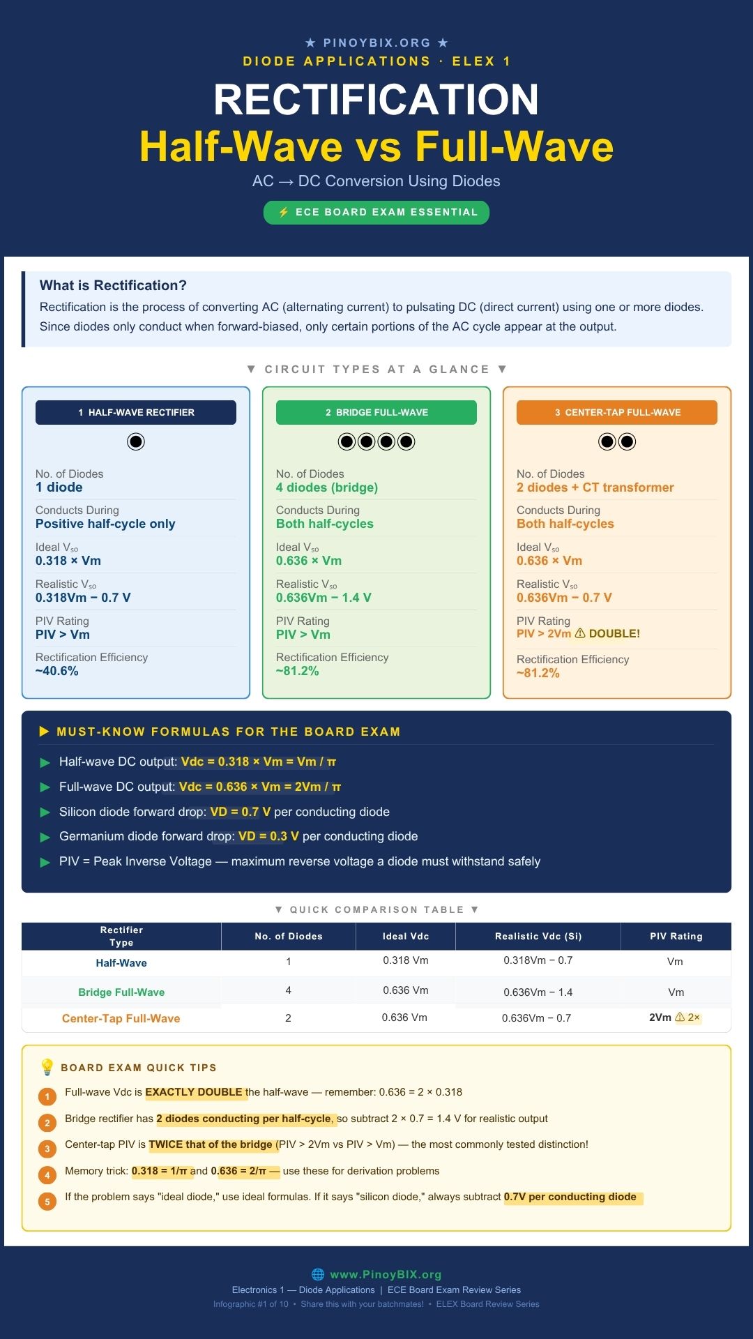
Rectification is the first circuit every electronics student builds, and it is also the first topic the board exam tests heavily. If you cannot tell a half-wave circuit from a bridge circuit on sight, or you mix up PIV ratings between center-tap and bridge rectifiers, you will lose points on items that should be free. This post walks through all three rectifier types the way you need to know them for the ECE board exam — the circuit behavior, the formulas, and the ten kinds of problems examiners actually write.
This is Part 1 of the Diode Applications ECE Board Exam Reviewer Series on PinoyBIX.org. We start with rectification because it is the most direct and testable application of a single diode: one component, one rule, three circuit configurations, and a set of formulas you must know cold before exam day. If you are reviewing for the ECE or EE board exam or currently enrolled in Electronics 1, save this page.
- ECE (Electronics Engineer) — Rectification is a core topic in Electronics Engineering and Electronic Systems and Technologies subjects. Expect 3 to 6 items covering all three rectifier types, PIV ratings, ripple factor, and practical diode drops. This is a high-frequency topic for ECE reviewees.
- EE (Electrical Engineer) — Appears in Electronics Engineering fundamentals. Rectifier circuits, PIV selection, and DC output calculations are tested at moderate to high frequency. Practical diode drops and efficiency values are commonly included.
Bottom line: ECE examinees must master every section of this post including ripple factor, efficiency, and PIV distinctions. EE examinees must master the DC output formulas, practical diode drops, and PIV ratings for both bridge and center-tap configurations.
What Rectification Actually Does
Rectification converts AC — an alternating current that swings between positive and negative — into pulsating DC, a current that flows in only one direction. A diode makes this possible because it conducts only when forward-biased. When the anode is more positive than the cathode, the diode turns on and current flows. When the polarity reverses, the diode blocks and acts like an open switch.
Stack this simple behavior across one or more diodes in different arrangements and you get three rectifier configurations the board exam tests. Half-wave rectifiers appear in cheap low-current adapters where simplicity matters more than efficiency. Bridge rectifiers sit inside nearly every modern linear power supply and phone charger, converting 220 V or 110 V AC into raw DC. Center-tap rectifiers are less common in new designs today but appear often in board exam problems and older audio amplifier power supplies.
Half-Wave Rectifier
A half-wave rectifier uses a single diode. During the positive half-cycle, the diode is forward biased and conducts — the output follows the input. During the negative half-cycle, the diode blocks and the output sits at zero. Only half the input waveform reaches the load.
![\[V_{dc} = \dfrac{V_m}{\pi} = 0.318\,V_m \quad \text{(ideal diode)}\]](https://pinoybix.org/wp-content/ql-cache/quicklatex.com-358bfa953dde33ad4f0ca7678a26a57e_l3.png "Rendered by QuickLaTeX.com")
![\[V_{dc} = 0.318\,V_m - V_D \quad \text{(practical: subtract one diode drop)}\]](https://pinoybix.org/wp-content/ql-cache/quicklatex.com-7d94cb4485d67bb7614fe9786d5f7b24_l3.png "Rendered by QuickLaTeX.com")
![\[\text{PIV} > V_m\]](https://pinoybix.org/wp-content/ql-cache/quicklatex.com-5252c17d3887e9c31c965d5a33944d7a_l3.png "Rendered by QuickLaTeX.com")
For a silicon diode,  V. For germanium,
  V. Always check which material the problem specifies before computing practical output voltage.
Bridge Full-Wave Rectifier
A bridge rectifier uses four diodes arranged so that two conduct during the positive half-cycle and the other two conduct during the negative half-cycle. Both half-cycles contribute to the output, which doubles the average DC voltage compared to half-wave and requires no center-tapped transformer.
![\[V_{dc} = \dfrac{2V_m}{\pi} = 0.636\,V_m \quad \text{(ideal diode)}\]](https://pinoybix.org/wp-content/ql-cache/quicklatex.com-d2ce24afa2aa00fd267548b373791d32_l3.png "Rendered by QuickLaTeX.com")
![\[V_{dc} = 0.636\,V_m - 2V_D \quad \text{(practical: two diodes conduct in series per half-cycle)}\]](https://pinoybix.org/wp-content/ql-cache/quicklatex.com-79cc12a23282c9b5c276cf0b207305bd_l3.png "Rendered by QuickLaTeX.com")
Two diodes conduct in series during each half-cycle, so subtract two diode drops, not one. This is the most commonly missed detail on bridge rectifier problems.
Center-Tap Full-Wave Rectifier
A center-tap rectifier uses two diodes and a transformer with a center-tapped secondary winding. Each diode conducts during one half-cycle, using one half of the secondary winding at a time. The DC output formula matches the bridge rectifier, but two critical differences set it apart on the board exam: only one diode conducts at a time, and the PIV rating doubles.
![\[V_{dc} = 0.636\,V_m - V_D \quad \text{(practical: only one diode conducts at a time)}\]](https://pinoybix.org/wp-content/ql-cache/quicklatex.com-15777fd108c6c27dbe6c45ae5521f6ce_l3.png "Rendered by QuickLaTeX.com")
![\[\text{PIV} > 2V_m \quad \text{(double the bridge requirement)}\]](https://pinoybix.org/wp-content/ql-cache/quicklatex.com-e923e477a005dce826ed8d78957f30f5_l3.png "Rendered by QuickLaTeX.com")
When a diode is reverse biased in a center-tap circuit, it sees the full secondary voltage across both winding halves — not just one half. That is why PIV jumps to  . This single distinction is the most frequently tested difference between bridge and center-tap configurations.
Ripple Factor, Efficiency, and Form Factor
Vdc tells you the average output but not how smooth it is. Three additional figures of merit quantify rectifier quality and the board exam tests all three. Memorize the constants — exam items on these quantities are often recall items, not derivation problems.
![\[\text{Ripple factor: } r = \dfrac{V_{ac}}{V_{dc}} = \sqrt{\left(\dfrac{V_{rms}}{V_{dc}}\right)^2 - 1}\]](https://pinoybix.org/wp-content/ql-cache/quicklatex.com-b449e286914f51341de1e08f71adeb45_l3.png "Rendered by QuickLaTeX.com")
![\[\text{Rectification efficiency: } \eta = \dfrac{P_{dc}}{P_{ac}} \times 100\%\]](https://pinoybix.org/wp-content/ql-cache/quicklatex.com-b1e014c49fe5112825289d1ae1845320_l3.png "Rendered by QuickLaTeX.com")
![\[\text{Form factor: } FF = \dfrac{V_{rms}}{V_{dc}}\]](https://pinoybix.org/wp-content/ql-cache/quicklatex.com-41e016f7d546aa369f7452631da65a54_l3.png "Rendered by QuickLaTeX.com")
| Parameter | Half-Wave | Full-Wave (Bridge or Center-Tap) |
|---|---|---|
| Ripple factor (r) | 1.21 | 0.482 |
| Efficiency (η) | 40.6% | 81.2% |
| Form factor (FF) | 1.57 | 1.11 |
| Output frequency | Same as input (f) | Double input (2f) |
Common Real-World Parts
The 1N4001 through 1N4007 series covers the most widely used rectifier diodes in low to medium power supplies, with PIV ratings from 50 V (1N4001) up to 1000 V (1N4007). The 1N5400 series handles 3 A for higher current applications. You will not be asked to memorize every part number for the board exam, but recognizing 1N4001 as a standard rectifier diode helps you read circuit diagrams faster on design-type items.
Where You Will Find This in Real Equipment
Bridge rectifiers sit inside nearly every wall adapter, phone charger, and linear regulated power supply, converting AC line voltage into raw DC before a regulator stage smooths it further. Half-wave rectifiers appear in cheap low-current chargers and some signal demodulation circuits where simplicity matters more than ripple. Center-tap rectifiers are found in older audio power amplifiers and some industrial supplies that still use center-tapped transformers from earlier designs.
Worked Problems — Board Exam Type Questions
The following 10 problems are representative of actual ECE and EE board exam questions on rectifier circuits. Work each problem by hand before reading the solution.
Problem 1 — ECE Board Exam Type
A half-wave rectifier is connected to a transformer secondary with a peak voltage of 30 V. Using an ideal diode, find Vdc.
Given: Half-wave rectifier,  V, ideal diode
Find: 
Solution:
Step 1: Since the diode is ideal, there is zero forward voltage drop. Apply the ideal half-wave formula directly.
![\[V_{dc} = 0.318 \times V_m\]](https://pinoybix.org/wp-content/ql-cache/quicklatex.com-14ca1f74a6e08046eeefdb490beb77c9_l3.png "Rendered by QuickLaTeX.com")
Step 2: Substitute and compute.
![\[V_{dc} = 0.318 \times 30 = 9.54 \text{ V}\]](https://pinoybix.org/wp-content/ql-cache/quicklatex.com-408a009b5c7d9714c102b9b9eac8e658_l3.png "Rendered by QuickLaTeX.com")
 V
V
Examiner note: “Ideal diode” means zero forward voltage drop. Students who automatically subtract 0.7 V here lose the item even though their method is otherwise correct. Always read the diode condition stated in the problem before substituting.
Problem 2 — ECE Board Exam Type
Repeat Problem 1 using a silicon diode instead of an ideal diode. Find the practical Vdc.
Given: Half-wave rectifier, V, silicon diode ( V)
Find: (practical)
Solution:
Step 1: Start from the ideal half-wave output.
![\[V_{dc(ideal)} = 0.318 \times 30 = 9.54 \text{ V}\]](https://pinoybix.org/wp-content/ql-cache/quicklatex.com-228a59f34433782df6397fee7949ad2e_l3.png "Rendered by QuickLaTeX.com")
Step 2: Subtract one silicon diode drop. Only one diode conducts at a time in a half-wave circuit.
![\[V_{dc} = 9.54 - 0.7 = 8.84 \text{ V}\]](https://pinoybix.org/wp-content/ql-cache/quicklatex.com-4e414ca6e451193ace1ba8e1943ea2b9_l3.png "Rendered by QuickLaTeX.com")
 V
V
Examiner note: Subtract only one diode drop here because only one diode conducts per cycle in a half-wave rectifier. Subtracting two drops (a bridge mistake carried over to this circuit) is a common error when students switch between rectifier types mid-exam.
Problem 3 — ECE Board Exam Type
A bridge rectifier has a transformer secondary peak voltage of 25 V. Using ideal diodes, find Vdc and the minimum PIV rating required for each diode.
Given: Bridge rectifier,  V, ideal diodes
Find: and minimum PIV
Solution:
Step 1: Apply the ideal full-wave formula for Vdc.
![\[V_{dc} = 0.636 \times 25 = 15.9 \text{ V}\]](https://pinoybix.org/wp-content/ql-cache/quicklatex.com-6aa87d53640a58718498dec0f3523a26_l3.png "Rendered by QuickLaTeX.com")
Step 2: Apply the bridge PIV rule. Each diode must withstand the peak input voltage during its non-conducting half-cycle.
![\[\text{PIV} > V_m = 25 \text{ V}\]](https://pinoybix.org/wp-content/ql-cache/quicklatex.com-8aef11ae9bd10af99891b1b0c11fc42d_l3.png "Rendered by QuickLaTeX.com")
 V, PIV
  V
V
Examiner note: Bridge PIV is  , not . Students who confuse this with the center-tap configuration will select the wrong diode rating. The rule applies only to center-tap rectifiers.
Problem 4 — ECE Board Exam Type
Repeat Problem 3 using silicon diodes. Find the practical Vdc.
Given: Bridge rectifier, V, silicon diodes ( V)
Find: (practical)
Solution:
Step 1: Start from the ideal full-wave output.
![\[V_{dc(ideal)} = 0.636 \times 25 = 15.9 \text{ V}\]](https://pinoybix.org/wp-content/ql-cache/quicklatex.com-e57e78b169504303bb7b049f59c52433_l3.png "Rendered by QuickLaTeX.com")
Step 2: Subtract two silicon diode drops. In a bridge circuit, two diodes conduct in series during each half-cycle.
![\[V_{dc} = 15.9 - 2(0.7) = 15.9 - 1.4 = 14.5 \text{ V}\]](https://pinoybix.org/wp-content/ql-cache/quicklatex.com-2e9522e8bc49f00ee8055eaf60320081_l3.png "Rendered by QuickLaTeX.com")
 V
V
Examiner note: Two diodes conduct in series per half-cycle in a bridge circuit, so subtract  V, not 0.7 V. Subtracting only one drop is the single most common error on bridge rectifier practical problems.
Problem 5 — ECE Board Exam Type
A center-tap rectifier has a peak voltage of 25 V measured from the center tap to one end of the secondary. Using ideal diodes, find Vdc and the minimum PIV rating for each diode.
Given: Center-tap rectifier, V per half secondary, ideal diodes
Find: and minimum PIV
Solution:
Step 1: Apply the ideal full-wave formula. Both bridge and center-tap use the same Vdc formula.
Step 2: Apply the center-tap PIV rule. The non-conducting diode sees the full secondary voltage across both winding halves during its reverse half-cycle.
![\[\text{PIV} > 2V_m = 2 \times 25 = 50 \text{ V}\]](https://pinoybix.org/wp-content/ql-cache/quicklatex.com-32dcf27423af9b70e46b9bd3013e85d9_l3.png "Rendered by QuickLaTeX.com")
V, PIV  V
V
Examiner note: Same Vdc as the bridge circuit in Problem 3, but the PIV doubles. The board exam frequently pairs Problems 3 and 5 as comparison items to test whether you know this distinction. If both answers look the same to you, you missed the PIV difference.
Problem 6 — EE Board Exam Type
A half-wave rectifier delivers Vdc = 9 V to a load. Find the RMS value of the AC ripple component.
Given: Half-wave rectifier,  V
V
Find:  (RMS ripple voltage)
Solution:
Step 1: Recall the half-wave ripple factor constant.
![\[r = 1.21 \quad \text{(half-wave)}\]](https://pinoybix.org/wp-content/ql-cache/quicklatex.com-1f9e9d1734e737ffa2e6f34ab646afba_l3.png "Rendered by QuickLaTeX.com")
Step 2: Apply the ripple factor definition and solve for .
![\[r = \dfrac{V_{ac}}{V_{dc}} \implies V_{ac} = r \times V_{dc} = 1.21 \times 9 = 10.89 \text{ V}\]](https://pinoybix.org/wp-content/ql-cache/quicklatex.com-574921d6b68788a9513a56e63945fe91_l3.png "Rendered by QuickLaTeX.com")
 V
V
Examiner note: The ripple voltage is larger than Vdc itself in a half-wave circuit — ripple factor 1.21 means the AC component exceeds the DC component. This is exactly why half-wave rectifiers need heavy filtering in real power supplies.
Problem 7 — EE Board Exam Type
A full-wave bridge rectifier is supplied by a 60 Hz AC source. Find the output ripple frequency.
Given: Full-wave bridge rectifier,  Hz
Hz
Find: Output ripple frequency 
Solution:
Step 1: Recall the full-wave frequency rule. Full-wave circuits produce two output pulses per input cycle — one from the positive half and one from the negative half.
Step 2: Apply the doubling relationship.
![\[f_{out} = 2 \times f_{in} = 2 \times 60 = 120 \text{ Hz}\]](https://pinoybix.org/wp-content/ql-cache/quicklatex.com-7bc00f994b6a87e0c215015c2534bafc_l3.png "Rendered by QuickLaTeX.com")
 Hz
Hz
Examiner note: Half-wave keeps the same frequency as the input since only one pulse occurs per full cycle. Full-wave doubles it. This is a recall item — no derivation needed once you know the rule.
Problem 8 — ECE Board Exam Type
What is the rectification efficiency of an ideal full-wave bridge rectifier?
Given: Ideal full-wave rectifier (bridge or center-tap)
Find: Rectification efficiency 
Solution:
Step 1: Recall the standard efficiency constant for any ideal full-wave configuration. This value comes from the ratio  and is fixed regardless of input voltage or frequency.
![\[\eta = 81.2\%\]](https://pinoybix.org/wp-content/ql-cache/quicklatex.com-c9dff71bacc7802e01bafa10fea08c24_l3.png "Rendered by QuickLaTeX.com")

Examiner note: Do not derive this during the exam unless the problem specifically asks for the derivation. Memorize 40.6% for half-wave and 81.2% for full-wave. Full-wave efficiency is exactly double half-wave efficiency, which is a useful cross-check.
Problem 9 — ECE Board Exam Type
A center-tap rectifier uses germanium diodes with a peak half-secondary voltage of 18 V. Find the practical Vdc.
Given: Center-tap rectifier,  V per half secondary, germanium diodes ( V)
Find: (practical)
Solution:
Step 1: Compute the ideal full-wave output.
![\[V_{dc(ideal)} = 0.636 \times 18 = 11.45 \text{ V}\]](https://pinoybix.org/wp-content/ql-cache/quicklatex.com-9b86a41e0d2c1faefc4582114217f912_l3.png "Rendered by QuickLaTeX.com")
Step 2: Subtract one germanium diode drop. Only one diode conducts at a time in a center-tap circuit.
![\[V_{dc} = 11.45 - 0.3 = 11.15 \text{ V}\]](https://pinoybix.org/wp-content/ql-cache/quicklatex.com-96f196ec8e2869527e707032145a6b16_l3.png "Rendered by QuickLaTeX.com")
 V
V
Examiner note: Germanium drops 0.3 V, silicon drops 0.7 V. This problem tests whether you read the diode material carefully. Substituting 0.7 V instead of 0.3 V gives 11.15 V vs 10.75 V — both are listed as choices on board exam items of this type to trap students who skim the problem statement.
Problem 10 — ECE Board Exam Type
A bridge rectifier is being designed for a transformer secondary with  V. Two diodes are available: 1N4001 (PIV 50 V) and 1N4004 (PIV 400 V). Which diode is the correct selection, and why?
Given: Bridge rectifier, V, diode options: 1N4001 (50 V PIV), 1N4004 (400 V PIV)
Find: Correct diode selection with justification
Solution:
Step 1: Determine the minimum PIV requirement for a bridge rectifier.
![\[\text{PIV} > V_m = 40 \text{ V}\]](https://pinoybix.org/wp-content/ql-cache/quicklatex.com-5a6ec963734870fa4bfe520bd77c9b0a_l3.png "Rendered by QuickLaTeX.com")
Step 2: Check both options against this requirement. The 1N4001 at 50 V PIV technically meets the minimum with only a 10 V margin. The 1N4004 at 400 V PIV provides a large margin against transient voltage spikes on the AC line.
Step 3: Apply engineering judgment. Real AC lines carry voltage spikes and surges that exceed the nominal peak. A 10 V safety margin is insufficient for reliable operation.
Examiner note: Design-type items test engineering judgment, not just formula substitution. The 1N4001 satisfies the mathematical minimum but fails the practical safety criterion. A competent engineer never rates a component at its absolute limit.
Common Mistakes and Examiner Traps
These are the most consistent error patterns on ECE and EE board exam problems covering rectifier circuits.
| ❌ Common Mistake | ✔ Correct Approach |
|---|---|
| Using PIV > Vm for a center-tap rectifier. Students copy the bridge rule without checking the circuit type. | Center-tap PIV is  — double the bridge requirement. The non-conducting diode sees the full secondary voltage across both winding halves. — double the bridge requirement. The non-conducting diode sees the full secondary voltage across both winding halves. |
| Subtracting only 0.7 V for a bridge rectifier practical output. Students treat it the same as a half-wave or center-tap circuit. | Subtract V for silicon in a bridge circuit. Two diodes conduct in series per half-cycle, so two drops must be subtracted. |
| Subtracting a diode drop when the problem says “ideal diode.” A reflex subtraction of 0.7 V regardless of what the problem states. | Ideal diode means zero forward drop. Use the 0.318 or 0.636 formula without any subtraction. Read the diode condition in the problem first. |
| Assuming half-wave and full-wave have the same output ripple frequency. Students forget the frequency doubling in full-wave circuits. | Full-wave output frequency is  because both half-cycles produce a pulse. Half-wave stays at because both half-cycles produce a pulse. Half-wave stays at  since only one half-cycle conducts. since only one half-cycle conducts. |
| Using silicon diode drop for a germanium diode problem. Students default to 0.7 V without checking diode material. | Silicon drops 0.7 V. Germanium drops 0.3 V. The diode material is always stated in the problem — read it before substituting. |
Board Exam Quick Tips
- Memorize
 and
and  . Full-wave Vdc is exactly double half-wave for the same . This relationship is a built-in answer check.
 - Center-tap PIV is always double the bridge PIV. This single fact is the most frequently tested distinction between the two full-wave configurations. Write it on your formula sheet.
- Memorize the four standard constants cold: 1.21, 0.482, 40.6%, 81.2%. Ripple factor and efficiency items are often pure recall — no derivation, no computation, just the number.
- Read the diode condition before you compute. Ideal, silicon, or germanium — this single word changes your answer. Make it a habit to underline this in the problem before writing anything.
- Bridge always subtracts two drops, half-wave and center-tap subtract one. Count the diodes in series in the conduction path, then subtract that many drops.
Frequently Asked Questions
Q1. Why does a center-tap rectifier need double the PIV rating of a bridge rectifier?
In a center-tap circuit, the non-conducting diode sees the full secondary voltage across both winding halves during the reverse half-cycle — not just one half. The bridge circuit distributes this voltage differently across four diodes so each one only blocks . Different topology, different PIV requirement.
Q2. Is a bridge rectifier always better than a center-tap rectifier?
For most modern designs, yes, because the bridge needs a simpler transformer and gives each diode a lower PIV requirement. Center-tap rectifiers remain useful when the design specifically requires a grounded center reference point, which some audio and instrumentation circuits need.
Q3. Why is half-wave rectifier efficiency capped at 40.6% even with ideal diodes?
The 40.6% figure is a fixed mathematical result of using only half the input waveform. It comes from the ratio of DC power to AC power supplied. No diode improvement changes this number because the limit depends on topology, not component quality.
Q4. Do I need to memorize the derivation of ripple factor and efficiency for the board exam?
Understand where the formulas come from, but prioritize application over derivation. Board exam items almost always test the constants themselves — 1.21, 0.482, 40.6%, 81.2% — not the derivation steps. Knowing when to apply each constant is the higher-value skill.
Q5. What happens if I use a diode with a PIV rating lower than required?
The diode breaks down during the reverse-biased portion of the cycle, typically through avalanche breakdown, and is permanently damaged. This is why design-type board exam items test PIV selection with a safety margin, not the bare mathematical minimum.
What Is Next
Now that you can analyze all three rectifier types, the next post in this series covers Diode Configurations: Series, Parallel, and Series-Parallel Networks, where you will apply the same diode models to more complex multi-diode circuits and learn which configuration rules matter most on the board exam.
→ Continue to Part 2 — Diode Configurations: Series, Parallel, and Series-Parallel Networks
→ Back to the Diode Applications ECE Board Exam Reviewer Series Index
Published by PinoyBIX.org — Engineering Education for Every Filipino Student. Electronics · Mathematics · Board Exam Review · Free for Everyone.
Related Content




P inoyBIX educates thousands of reviewers and students a day in preparation for their board examinations. Also provides professionals with materials for their lectures and practice exams. Help me go forward with the same spirit.
“Will you subscribe today via YOUTUBE?”
TIRED OF ADS?
- Become Premium Member and experienced complete ads-free content browsing.
- Full Content Access to Premium Solutions Exclusive for Premium members
- Access to PINOYBIX FREEBIES folder
- Download Reviewers and Learning Materials Free
- Download Content: You can see download/print button at the bottom of each post.
PINOYBIX FREEBIES FOR PREMIUM MEMBERSHIP:
- CIVIL ENGINEERING REVIEWER
- CIVIL SERVICE EXAM REVIEWER
- CRIMINOLOGY REVIEWER
- ELECTRONICS ENGINEERING REVIEWER (ECE/ECT)
- ELECTRICAL ENGINEERING & RME REVIEWER
- FIRE OFFICER EXAMINATION REVIEWER
- LET REVIEWER
- MASTER PLUMBER REVIEWER
- MECHANICAL ENGINEERING REVIEWER
- NAPOLCOM REVIEWER
- Additional upload reviewers and learning materials are also FREE
FOR A LIMITED TIME
If you subscribe for PREMIUM today!
You will receive an additional 1 month of Premium Membership FREE.
For Bronze Membership an additional 2 months of Premium Membership FREE.
For Silver Membership an additional 3 months of Premium Membership FREE.
For Gold Membership an additional 5 months of Premium Membership FREE.
Join the PinoyBIX community.