
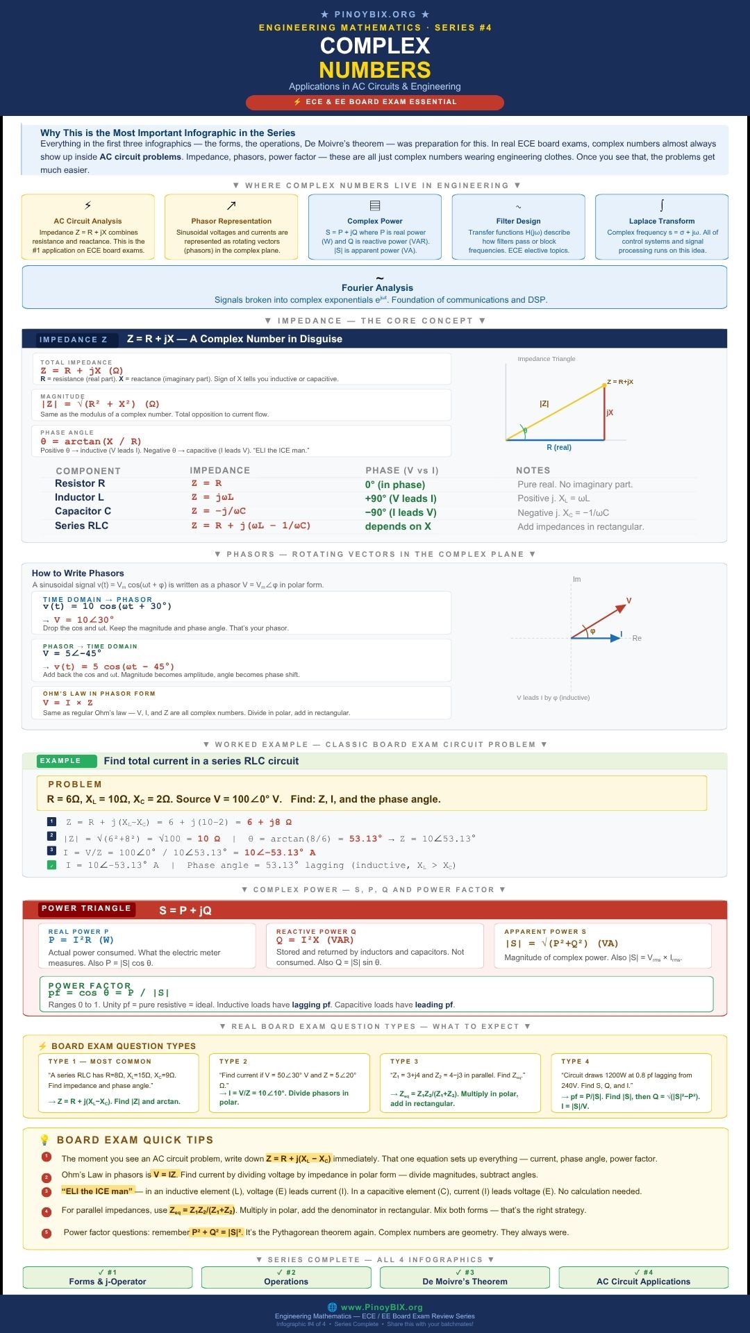
Everything in the first three parts of this series was preparation for this. The four forms, the operations, De Moivre’s theorem — all of it points here. In real engineering board exams, complex numbers almost never appear as pure algebra problems. They appear dressed as AC circuit problems. Impedance, phasors, power factor, apparent power — these are all complex numbers with engineering labels attached. Once you see that clearly, entire sections of the board exam become straightforward.
This is Part 4 of the Complete Complex Numbers ECE and EE Board Exam Reviewer Series on PinoyBIX.org. Part 1 covered the four forms. Part 2 covered operations. Part 3 covered De Moivre’s theorem. This final part connects all of it to real circuit problems with worked examples and every major board exam question type in this topic.
- ECE (Electronics Engineer) — AC circuit analysis using complex numbers is one of the highest-weight topics on the ECE board exam. Impedance, phasor voltage and current, Ohm’s law in phasor form, complex power, and power factor all appear regularly. Expect 6 to 12 items across Engineering Mathematics and Electronics subjects. This is a critical topic.
- EE (Electrical Engineer) — This is the core application topic of the entire EE board exam. Phasor analysis, impedance of RLC circuits, series and parallel impedance combinations, complex power, power factor correction — all are tested heavily. Very high frequency. Mastery is non-negotiable.
- ME (Mechanical Engineer) — Complex numbers in AC circuits appear in Engineering Mathematics and occasionally in Electrical Technology subjects. Impedance of series RLC circuits and basic phasor representation are the most tested. Moderate frequency.
- CE (Civil Engineer) — Basic AC circuit analysis appears in Engineering Mathematics. Impedance and power factor calculations appear occasionally. Low to moderate frequency.
- ChE (Chemical Engineer) — Complex numbers in process control transfer functions use the same mathematics as AC circuit analysis. The variable
 in Laplace transforms is a direct extension of phasor concepts. Moderate frequency in Engineering Mathematics and Chemical Engineering subjects.
 - GeE (Geodetic Engineer) — Basic AC circuit concepts appear in Engineering Mathematics. Low frequency.
- Naval Architect and Marine Engineer — AC circuit analysis and vibration analysis both use complex numbers. Impedance and phasor problems appear in Engineering Mathematics and Marine Electrical subjects. Moderate frequency.
 in Laplace transforms is a direct extension of phasor concepts. Moderate frequency in Engineering Mathematics and Chemical Engineering subjects.
Bottom line: ECE and EE examinees must master every section of this post completely. ME, ChE, and Naval Architecture examinees must master impedance and basic phasor analysis. All other boards need a working understanding of the impedance formula and power factor.
Why AC Circuits Use Complex Numbers
In a DC circuit, resistance is the only opposition to current flow. It is a single real number measured in ohms. In an AC circuit, inductors and capacitors also oppose current — but in a frequency-dependent way that shifts the phase between voltage and current. A single real number cannot capture both the magnitude and the phase shift simultaneously.
Complex numbers solve this problem exactly. The real part carries the resistive component. The imaginary part carries the reactive component. The angle between them is the phase shift. One complex number describes everything about how a component or circuit behaves under AC conditions.
In DC circuits:  where
where  is a real number.
In AC circuits:  where
where  is a complex number.
The real part is resistance. The imaginary part  is reactance. The angle
  is the phase difference between voltage and current.
Impedance — 

Impedance  is the total opposition to AC current flow. It is a complex number in rectangular form where the real part is resistance and the imaginary part is reactance.
![\[\mathbf{Z} = R + jX \quad (\Omega)\]](https://pinoybix.org/wp-content/ql-cache/quicklatex.com-3dfa15369a5e3980214841ab57f92b38_l3.png "Rendered by QuickLaTeX.com")
![\[|\mathbf{Z}| = \sqrt{R^2 + X^2} \quad (\Omega)\]](https://pinoybix.org/wp-content/ql-cache/quicklatex.com-eae069a8314afd247b8ddde301fc1e5d_l3.png "Rendered by QuickLaTeX.com")
![\[\theta = \arctan\!\left(\dfrac{X}{R}\right)\]](https://pinoybix.org/wp-content/ql-cache/quicklatex.com-f46504a9426e0537b5c2a0fea4d52f22_l3.png "Rendered by QuickLaTeX.com")
where is resistance in ohms, is reactance in ohms,  is the magnitude of impedance, and
  is the phase angle.
The sign of the reactance tells you whether the circuit is inductive or capacitive.
- Positive
 means inductive reactance. The circuit is inductive. Voltage leads current.
 - Negative means capacitive reactance. The circuit is capacitive. Current leads voltage.
 means purely resistive. Voltage and current are in phase.
 means purely resistive. Voltage and current are in phase.
Impedance of Individual Components
| Component | Impedance | Phase (V vs I) | Reactance |
|---|---|---|---|
| Resistor |
 |
 — in phase — in phase |
No reactance |
Inductor  |
 |
 — V leads I — V leads I |
 |
Capacitor  |
 |
 — I leads V — I leads V |
 |
where  is the angular frequency in radians per second.
Series RLC Circuit Impedance
For a series RLC circuit, the total impedance is the sum of the individual impedances.
![\[\mathbf{Z}_{total} = R + j(X_L - X_C) = R + j\!\left(\omega L - \dfrac{1}{\omega C}\right)\]](https://pinoybix.org/wp-content/ql-cache/quicklatex.com-62d74130b7e25531c9623a5ebc94e2de_l3.png "Rendered by QuickLaTeX.com")
![\[|\mathbf{Z}_{total}| = \sqrt{R^2 + (X_L - X_C)^2}\]](https://pinoybix.org/wp-content/ql-cache/quicklatex.com-dc3641ca74d4ae7ef4787c545e926241_l3.png "Rendered by QuickLaTeX.com")
![\[\theta = \arctan\!\left(\dfrac{X_L - X_C}{R}\right)\]](https://pinoybix.org/wp-content/ql-cache/quicklatex.com-0ba823218a4c750d930235ddfd22586d_l3.png "Rendered by QuickLaTeX.com")
When  , the net reactance is positive and the circuit is inductive. When
  , the net reactance is negative and the circuit is capacitive. When
  , the circuit is at resonance and
  .
.
Phasors — Representing Sinusoidal Signals as Complex Numbers
A sinusoidal voltage or current varies with time. Writing it as a time function in every calculation is tedious. Phasor representation solves this by converting the time domain signal into a complex number — a fixed vector in the complex plane whose magnitude is the amplitude and whose angle is the phase.
Time domain to phasor:
![\[v(t) = V_m\cos(\omega t + \phi) \quad \longrightarrow \quad \mathbf{V} = V_m\angle\phi\]](https://pinoybix.org/wp-content/ql-cache/quicklatex.com-cc4fc6df8816350da7cebeb2df956534_l3.png "Rendered by QuickLaTeX.com")
Drop the  and
and  . Keep the amplitude and phase angle.
Phasor to time domain:
![\[\mathbf{V} = V_m\angle\phi \quad \longrightarrow \quad v(t) = V_m\cos(\omega t + \phi)\]](https://pinoybix.org/wp-content/ql-cache/quicklatex.com-96a4b32ad61016f8e7fbd72ec928d009_l3.png "Rendered by QuickLaTeX.com")
Add back the and . The magnitude becomes the amplitude.
Important: phasors assume all signals in the circuit share the same frequency  . The phasor captures only the amplitude and phase — not the frequency. This is why phasor analysis works only for single-frequency AC circuits.
Ohm’s Law in Phasor Form
![\[\mathbf{V} = \mathbf{I} \cdot \mathbf{Z}\]](https://pinoybix.org/wp-content/ql-cache/quicklatex.com-a5e355bf8426cc576889525874b89c9f_l3.png "Rendered by QuickLaTeX.com")
![\[\mathbf{I} = \dfrac{\mathbf{V}}{\mathbf{Z}}\]](https://pinoybix.org/wp-content/ql-cache/quicklatex.com-4259e022e2703ce20f6cbd1d437ee5a4_l3.png "Rendered by QuickLaTeX.com")
![\[\mathbf{Z} = \dfrac{\mathbf{V}}{\mathbf{I}}\]](https://pinoybix.org/wp-content/ql-cache/quicklatex.com-a78b91e84a4c41c496cee7e6ee3c6648_l3.png "Rendered by QuickLaTeX.com")
These are exactly the same as DC Ohm’s law except that  ,
,  , and are all complex numbers. Multiply and divide them using polar form: multiply magnitudes and add or subtract angles.
The memory device “ELI the ICE man” tells you the phase relationship without calculation.
- ELI — In an inductor (L), voltage (E) leads current (I). The current lags.
- ICE — In a capacitor (C), current (I) leads voltage (E). The current leads.
Complex Power —  ,
,  ,
,  , and Power Factor
 ,
, Power in AC circuits has three components, each representing a different aspect of energy behavior. Together they form the power triangle, which is geometrically identical to the impedance triangle.
![\[\mathbf{S} = P + jQ \quad \text{(complex power, VA)}\]](https://pinoybix.org/wp-content/ql-cache/quicklatex.com-d6a5f99de48fe32bc18e8444615d0e3e_l3.png "Rendered by QuickLaTeX.com")
![\[P = |\mathbf{S}|\cos\theta = I_{rms}^2 R \quad \text{(real power, W)}\]](https://pinoybix.org/wp-content/ql-cache/quicklatex.com-fdf43495c3f9a9964bacc96ce5bb0485_l3.png "Rendered by QuickLaTeX.com")
![\[Q = |\mathbf{S}|\sin\theta = I_{rms}^2 X \quad \text{(reactive power, VAR)}\]](https://pinoybix.org/wp-content/ql-cache/quicklatex.com-748868e328b568ad1f0dc99caa8b0627_l3.png "Rendered by QuickLaTeX.com")
![\[|\mathbf{S}| = \sqrt{P^2 + Q^2} = V_{rms} \cdot I_{rms} \quad \text{(apparent power, VA)}\]](https://pinoybix.org/wp-content/ql-cache/quicklatex.com-01ec94c374024ce6f835936733a90427_l3.png "Rendered by QuickLaTeX.com")
![\[\text{pf} = \cos\theta = \dfrac{P}{|\mathbf{S}|} \quad \text{(power factor)}\]](https://pinoybix.org/wp-content/ql-cache/quicklatex.com-c46b72ebca5f63529984561e47bc97e1_l3.png "Rendered by QuickLaTeX.com")
Real power  is the actual energy consumed per second. It is what your electric meter measures. Reactive power
  is energy stored and returned by inductors and capacitors — it does no net work but increases the current demand. Apparent power
  is the product of rms voltage and rms current regardless of phase.
Power factor ranges from  to
to  . A power factor of means the load is purely resistive — all power delivered is consumed. A low power factor means significant reactive power is present, which wastes transmission capacity.
- Inductive loads have lagging power factor — current lags voltage.
- Capacitive loads have leading power factor — current leads voltage.
Parallel Impedance
For two impedances connected in parallel, the equivalent impedance uses the product over sum formula — the same as parallel resistance in DC circuits, but with complex number arithmetic.
![\[\mathbf{Z}_{eq} = \dfrac{\mathbf{Z}_1 \cdot \mathbf{Z}_2}{\mathbf{Z}_1 + \mathbf{Z}_2}\]](https://pinoybix.org/wp-content/ql-cache/quicklatex.com-a23a6bbe00dd9ccae96bf487f11fc724_l3.png "Rendered by QuickLaTeX.com")
Multiply the numerator in polar form. Add the denominator in rectangular form. Convert the denominator to polar for the final division.
Worked Problems — Board Exam Type Questions
The following 10 problems represent actual ECE, EE, ME, CE, and ChE board exam question types on complex numbers in AC circuits. Work each problem completely before reading the solution.
Problem 1 — ECE Board Exam Type
A series RLC circuit has  ,
,  , and
, and  . Find the total impedance in both rectangular and polar form.
Given: , ,
Find: in rectangular and polar form.
Solution:
Step 1: Write the total impedance in rectangular form.
![\[\mathbf{Z} = R + j(X_L - X_C) = 6 + j(10 - 2) = 6 + j8\,\Omega\]](https://pinoybix.org/wp-content/ql-cache/quicklatex.com-db06b4d5a3b8bb78921a070e5c42c1f6_l3.png "Rendered by QuickLaTeX.com")
Step 2: Find the magnitude.
![\[|\mathbf{Z}| = \sqrt{6^2 + 8^2} = \sqrt{36 + 64} = \sqrt{100} = 10\,\Omega\]](https://pinoybix.org/wp-content/ql-cache/quicklatex.com-7121906d3c9c51603ee052bb37652f56_l3.png "Rendered by QuickLaTeX.com")
Step 3: Find the phase angle. Since both and are positive, the angle is in Quadrant I.
![\[\theta = \arctan\!\left(\dfrac{8}{6}\right) = \arctan(1.333) = 53.13°\]](https://pinoybix.org/wp-content/ql-cache/quicklatex.com-dc11ed9813e8d61e8e726e14bce7d20b_l3.png "Rendered by QuickLaTeX.com")
Step 4: Write the polar form.
![\[\mathbf{Z} = 10\angle 53.13°\,\Omega\]](https://pinoybix.org/wp-content/ql-cache/quicklatex.com-94c5f623b5f7bf064958f9dc154f4251_l3.png "Rendered by QuickLaTeX.com")
 (rectangular) and
  (polar)
Examiner note: The 6-8-10 right triangle is a scaled version of the 3-4-5 triangle. Recognize it immediately.  and
and  without a calculator. This specific combination appears frequently on the board exam.
Problem 2 — EE Board Exam Type
A source voltage  V is applied to a circuit with impedance . Find the phasor current .
Given: V,
Find:
Solution:
Step 1: Apply Ohm’s law in phasor form.
![\[\mathbf{I} = \dfrac{\mathbf{V}}{\mathbf{Z}} = \dfrac{100\angle 0°}{10\angle 53.13°}\]](https://pinoybix.org/wp-content/ql-cache/quicklatex.com-d4682b2eb231f337e4262dd2ea6743f9_l3.png "Rendered by QuickLaTeX.com")
Step 2: Divide the magnitudes and subtract the angles.
![\[|\mathbf{I}| = \dfrac{100}{10} = 10\,\text{A}\]](https://pinoybix.org/wp-content/ql-cache/quicklatex.com-c57109d389bf7eb7601d745eb08665df_l3.png "Rendered by QuickLaTeX.com")
![\[\angle\mathbf{I} = 0° - 53.13° = -53.13°\]](https://pinoybix.org/wp-content/ql-cache/quicklatex.com-8d21892f79ddd27ee12808da6be6343d_l3.png "Rendered by QuickLaTeX.com")
Step 3: Write the result.
![\[\mathbf{I} = 10\angle{-53.13°}\,\text{A}\]](https://pinoybix.org/wp-content/ql-cache/quicklatex.com-521daefe8d7d67fb15310304aa2976c8_l3.png "Rendered by QuickLaTeX.com")
 A
A
Examiner note: The negative angle on the current confirms the circuit is inductive — current lags voltage by  . This matches the positive reactance
  from Problem 1. Always check that the sign of the current angle is consistent with the nature of the circuit reactance.
Problem 3 — ECE Board Exam Type
Convert the time domain voltage  V to phasor form. Then convert the phasor
  A back to time domain.
Given: V and A
Find: Phasor and time domain  .
.
Solution:
Step 1: Convert  to phasor form. Drop and . Keep amplitude and phase angle.
![\[\mathbf{V} = 311\angle 30°\,\text{V}\]](https://pinoybix.org/wp-content/ql-cache/quicklatex.com-c20ad4dd7428cc4f2e22fd5fc66d7999_l3.png "Rendered by QuickLaTeX.com")
Step 2: Convert A back to time domain. Add  .
.
![\[i(t) = 5\cos(\omega t - 45°)\,\text{A}\]](https://pinoybix.org/wp-content/ql-cache/quicklatex.com-6efb54068b15048c068092baf506b50e_l3.png "Rendered by QuickLaTeX.com")
 V and
V and  A
A
Examiner note: The amplitude in phasor form is the peak value  , not the rms value. If the problem gives rms voltage and asks for the phasor, use the peak value
  . If it asks for rms phasor directly, use the rms value as the magnitude. Read the problem statement carefully to determine which convention is required.
Problem 4 — ME Board Exam Type
A coil has resistance  and inductive reactance
  . Find the impedance, the phase angle, and state whether current leads or lags voltage.
Given: ,
Find: , , and the phase relationship.
Solution:
Step 1: Write the impedance in rectangular form. There is no capacitor so  .
.
![\[\mathbf{Z} = R + jX_L = 8 + j6\,\Omega\]](https://pinoybix.org/wp-content/ql-cache/quicklatex.com-927a27df525b28c766873f05ec5f6e5c_l3.png "Rendered by QuickLaTeX.com")
Step 2: Find the magnitude.
![\[|\mathbf{Z}| = \sqrt{8^2 + 6^2} = \sqrt{64 + 36} = \sqrt{100} = 10\,\Omega\]](https://pinoybix.org/wp-content/ql-cache/quicklatex.com-673f855075c3ad014d2145c62b3c765f_l3.png "Rendered by QuickLaTeX.com")
Step 3: Find the phase angle.
![\[\theta = \arctan\!\left(\dfrac{6}{8}\right) = \arctan(0.75) = 36.87°\]](https://pinoybix.org/wp-content/ql-cache/quicklatex.com-113b550218831ed32c9467785fff97d8_l3.png "Rendered by QuickLaTeX.com")
Step 4: Determine the phase relationship. The reactance is positive (inductive), so the circuit is inductive. By ELI: voltage leads current, or equivalently, current lags voltage by  .
.
 . Current lags voltage by (inductive circuit).
Examiner note: The 6-8-10 triangle (a scaled 3-4-5 triangle) gives directly. Recognize common Pythagorean triples in impedance problems to save computation time: 3-4-5, 5-12-13, 8-15-17, and their multiples.
Problem 5 — EE Board Exam Type
Two impedances  and
and  are connected in series. Find the total impedance and the total current if the source voltage is
  V.
V.
Given: , , V
Find:  and .
and .
Solution:
Step 1: Add the impedances in rectangular form. Series impedances add directly.
![\[\mathbf{Z}_{total} = \mathbf{Z}_1 + \mathbf{Z}_2 = (3 + 4) + j(4 - 3) = 7 + j1\,\Omega\]](https://pinoybix.org/wp-content/ql-cache/quicklatex.com-21a31c5e1c88016c508be7dc5fc2ba49_l3.png "Rendered by QuickLaTeX.com")
Step 2: Convert to polar form.
![\[|\mathbf{Z}_{total}| = \sqrt{7^2 + 1^2} = \sqrt{49 + 1} = \sqrt{50} = 5\sqrt{2} \approx 7.07\,\Omega\]](https://pinoybix.org/wp-content/ql-cache/quicklatex.com-17d8fc3b4b8367d29992bf214ea7bdd0_l3.png "Rendered by QuickLaTeX.com")
![\[\theta = \arctan\!\left(\dfrac{1}{7}\right) = 8.13°\]](https://pinoybix.org/wp-content/ql-cache/quicklatex.com-5a9f1835f5a67dab30d18119867dca09_l3.png "Rendered by QuickLaTeX.com")
![\[\mathbf{Z}_{total} = 7.07\angle 8.13°\,\Omega\]](https://pinoybix.org/wp-content/ql-cache/quicklatex.com-92694fd0b979401d7160e1982406e8a3_l3.png "Rendered by QuickLaTeX.com")
Step 3: Find the current using Ohm’s law.
![\[\mathbf{I} = \dfrac{\mathbf{V}}{\mathbf{Z}_{total}} = \dfrac{50\angle 0°}{7.07\angle 8.13°} = \dfrac{50}{7.07}\angle(0° - 8.13°) = 7.07\angle{-8.13°}\,\text{A}\]](https://pinoybix.org/wp-content/ql-cache/quicklatex.com-bf6fd4106c64982f8e8f6f0357371904_l3.png "Rendered by QuickLaTeX.com")
 and
and  A
A
Examiner note: Series impedances are always added in rectangular form. The result  has a small positive reactance, which means the combined circuit is slightly inductive. The small phase angle of
  confirms this — current lags voltage by only a small amount.
Problem 6 — ECE Board Exam Type
Two impedances and are connected in parallel. Find the equivalent impedance.
Given: ,
Find: 
Solution:
Step 1: Convert both impedances to polar form for multiplication.
![\[|\mathbf{Z}_1| = \sqrt{3^2 + 4^2} = 5\,\Omega \quad \theta_1 = \arctan\!\left(\dfrac{4}{3}\right) = 53.13° \quad \Rightarrow \quad \mathbf{Z}_1 = 5\angle 53.13°\]](https://pinoybix.org/wp-content/ql-cache/quicklatex.com-28c7e7d95b942a73469ea1f08360a312_l3.png "Rendered by QuickLaTeX.com")
![\[|\mathbf{Z}_2| = \sqrt{4^2 + (-3)^2} = 5\,\Omega \quad \theta_2 = \arctan\!\left(\dfrac{-3}{4}\right) = -36.87° \quad \Rightarrow \quad \mathbf{Z}_2 = 5\angle{-36.87°}\]](https://pinoybix.org/wp-content/ql-cache/quicklatex.com-8b603ab566a058fbbe802e0155c0fbef_l3.png "Rendered by QuickLaTeX.com")
Step 2: Multiply  in polar form.
![\[\mathbf{Z}_1 \cdot \mathbf{Z}_2 = (5 \times 5)\angle(53.13° + (-36.87°)) = 25\angle 16.26°\]](https://pinoybix.org/wp-content/ql-cache/quicklatex.com-7b28a0d752a1eafe040b0df5d79066ac_l3.png "Rendered by QuickLaTeX.com")
Step 3: Add  in rectangular form.
![\[\mathbf{Z}_1 + \mathbf{Z}_2 = (3 + 4) + j(4 - 3) = 7 + j1\,\Omega\]](https://pinoybix.org/wp-content/ql-cache/quicklatex.com-34d6d8fe2da833d9a47342f0b258a941_l3.png "Rendered by QuickLaTeX.com")
Step 4: Convert the denominator to polar form.
![\[|7 + j1| = \sqrt{49 + 1} = \sqrt{50} \approx 7.07\,\Omega \quad \theta = \arctan\!\left(\dfrac{1}{7}\right) = 8.13°\]](https://pinoybix.org/wp-content/ql-cache/quicklatex.com-e6956d2c360895ac552348dc357ec034_l3.png "Rendered by QuickLaTeX.com")
![\[\mathbf{Z}_1 + \mathbf{Z}_2 = 7.07\angle 8.13°\]](https://pinoybix.org/wp-content/ql-cache/quicklatex.com-f3511a85f211dad37c4c303245d46f06_l3.png "Rendered by QuickLaTeX.com")
Step 5: Divide numerator by denominator in polar form.
![\[\mathbf{Z}_{eq} = \dfrac{25\angle 16.26°}{7.07\angle 8.13°} = \dfrac{25}{7.07}\angle(16.26° - 8.13°) = 3.54\angle 8.13°\,\Omega\]](https://pinoybix.org/wp-content/ql-cache/quicklatex.com-10116ea75c8d045952e0ab1fb69d467a_l3.png "Rendered by QuickLaTeX.com")
Step 6: Convert to rectangular form.
![\[R = 3.54\cos 8.13° = 3.54(0.990) = 3.50\,\Omega\]](https://pinoybix.org/wp-content/ql-cache/quicklatex.com-d4d73383f5d5eddd0c15807cb8e9d71c_l3.png "Rendered by QuickLaTeX.com")
![\[X = 3.54\sin 8.13° = 3.54(0.141) = 0.50\,\Omega\]](https://pinoybix.org/wp-content/ql-cache/quicklatex.com-249f21f7378a93d91a178cdf4b087ed0_l3.png "Rendered by QuickLaTeX.com")
 or
or 
Examiner note: Parallel impedance always requires the product over sum formula. Multiply the numerator in polar form and add the denominator in rectangular form. Never add impedances in polar form directly. This mixed form approach is the correct and efficient method.
Problem 7 — EE Board Exam Type
A single-phase load draws  W at a power factor of
  lagging from a
  V rms source. Find the apparent power , reactive power , and the load current
  .
.
Given: W,  lagging,
  V
V
Find: , , and
Solution:
Step 1: Find the apparent power using the power factor definition.
![\[\text{pf} = \dfrac{P}{|\mathbf{S}|} \quad \Rightarrow \quad |\mathbf{S}| = \dfrac{P}{\text{pf}} = \dfrac{1{,}200}{0.8} = 1{,}500\,\text{VA}\]](https://pinoybix.org/wp-content/ql-cache/quicklatex.com-6bc661910bed146cac9adfa2dcd05c17_l3.png "Rendered by QuickLaTeX.com")
Step 2: Find the reactive power using the power triangle.
![\[|\mathbf{S}|^2 = P^2 + Q^2 \quad \Rightarrow \quad Q = \sqrt{|\mathbf{S}|^2 - P^2} = \sqrt{1{,}500^2 - 1{,}200^2}\]](https://pinoybix.org/wp-content/ql-cache/quicklatex.com-76a9d08fbdcca9074f52767c81a96fdb_l3.png "Rendered by QuickLaTeX.com")
![\[Q = \sqrt{2{,}250{,}000 - 1{,}440{,}000} = \sqrt{810{,}000} = 900\,\text{VAR}\]](https://pinoybix.org/wp-content/ql-cache/quicklatex.com-af6bbd5cff39556ee0d99ff32e0214ed_l3.png "Rendered by QuickLaTeX.com")
Step 3: Find the rms current.
![\[|\mathbf{S}| = V_{rms} \cdot I_{rms} \quad \Rightarrow \quad I_{rms} = \dfrac{|\mathbf{S}|}{V_{rms}} = \dfrac{1{,}500}{240} = 6.25\,\text{A}\]](https://pinoybix.org/wp-content/ql-cache/quicklatex.com-286ae9636d654c001d398a69666910b0_l3.png "Rendered by QuickLaTeX.com")
 VA,
VA,  VAR,
VAR,  A
A
Examiner note: The power triangle relationship  is the Pythagorean theorem applied to power. It is structurally identical to
  . A lagging power factor means the load is inductive, so is positive.
Problem 8 — CE Board Exam Type
A circuit has impedance  . Find the power factor and state whether it is leading or lagging.
Given:
Find: Power factor and its nature.
Solution:
Step 1: Find the magnitude of the impedance.
![\[|\mathbf{Z}| = \sqrt{5^2 + (-12)^2} = \sqrt{25 + 144} = \sqrt{169} = 13\,\Omega\]](https://pinoybix.org/wp-content/ql-cache/quicklatex.com-7b5cbaf9aae376268ad6d9f1a6177ce1_l3.png "Rendered by QuickLaTeX.com")
Step 2: Find the phase angle.
![\[\theta = \arctan\!\left(\dfrac{-12}{5}\right) = -67.38°\]](https://pinoybix.org/wp-content/ql-cache/quicklatex.com-374f1fb15bd40ad8f33b20e1fd41ac6b_l3.png "Rendered by QuickLaTeX.com")
Step 3: Compute the power factor.
![\[\text{pf} = \cos\theta = \cos(-67.38°) = 0.385\]](https://pinoybix.org/wp-content/ql-cache/quicklatex.com-2ffdfe6202287ff75017e7dd5bef0deb_l3.png "Rendered by QuickLaTeX.com")
Step 4: Determine the nature. The reactance is negative ( ), which means the circuit is capacitive. Capacitive circuits have leading power factor — current leads voltage.
 leading (capacitive circuit)
Examiner note: The 5-12-13 Pythagorean triple gives  directly. Negative reactance means capacitive means leading power factor. Positive reactance means inductive means lagging power factor. These three-part connections must be automatic on the board exam.
Problem 9 — ECE Board Exam Type
A series circuit has  and
and  mH. The source frequency is
  Hz. Find the impedance at this frequency and the current if
  V.
V.
Given: , mH, Hz, V
Find: and
Solution:
Step 1: Compute the angular frequency.
![\[\omega = 2\pi f = 2\pi(60) = 376.99\,\text{rad/s}\]](https://pinoybix.org/wp-content/ql-cache/quicklatex.com-395e1eff115f8c010981073645e92b1b_l3.png "Rendered by QuickLaTeX.com")
Step 2: Compute the inductive reactance.
![\[X_L = \omega L = 376.99 \times 0.03183 = 12\,\Omega\]](https://pinoybix.org/wp-content/ql-cache/quicklatex.com-5f9c2c6b71edd9fb33621704904de3bc_l3.png "Rendered by QuickLaTeX.com")
Step 3: Write the total impedance.
![\[\mathbf{Z} = R + jX_L = 10 + j12\,\Omega\]](https://pinoybix.org/wp-content/ql-cache/quicklatex.com-50492ed0ea574fac15225c9b2b90f993_l3.png "Rendered by QuickLaTeX.com")
Step 4: Convert to polar form.
![\[|\mathbf{Z}| = \sqrt{10^2 + 12^2} = \sqrt{100 + 144} = \sqrt{244} \approx 15.62\,\Omega\]](https://pinoybix.org/wp-content/ql-cache/quicklatex.com-d57a5079bb109c31c37bf641271a0018_l3.png "Rendered by QuickLaTeX.com")
![\[\theta = \arctan\!\left(\dfrac{12}{10}\right) = \arctan(1.2) = 50.19°\]](https://pinoybix.org/wp-content/ql-cache/quicklatex.com-1502452ef089a8650206b358586760bc_l3.png "Rendered by QuickLaTeX.com")
![\[\mathbf{Z} = 15.62\angle 50.19°\,\Omega\]](https://pinoybix.org/wp-content/ql-cache/quicklatex.com-fa495e64f117ee6f65fbecba9d248c19_l3.png "Rendered by QuickLaTeX.com")
Step 5: Find the current.
![\[\mathbf{I} = \dfrac{\mathbf{V}}{\mathbf{Z}} = \dfrac{120\angle 0°}{15.62\angle 50.19°} = 7.68\angle{-50.19°}\,\text{A}\]](https://pinoybix.org/wp-content/ql-cache/quicklatex.com-ee8af9bf7267eae17aee72fe1e4d6da0_l3.png "Rendered by QuickLaTeX.com")
 and
and  A
A
Examiner note: When a problem gives inductance in mH and frequency in Hz, always compute  as the first step. Substituting directly without computing first is a common source of error. Also note that mH is specifically chosen to give
  at
at  Hz — a deliberate board exam construction.
Problem 10 — EE Board Exam Type
A load draws complex power  VA from a
  V rms source. Find the power factor, the load impedance, and the load current.
Given: VA,  V
V
Find: pf,  , and
, and
Solution:
Step 1: Identify  W and
W and  VAR from the complex power.
Step 2: Find the apparent power.
![\[|\mathbf{S}| = \sqrt{P^2 + Q^2} = \sqrt{800^2 + 600^2} = \sqrt{640{,}000 + 360{,}000} = \sqrt{1{,}000{,}000} = 1{,}000\,\text{VA}\]](https://pinoybix.org/wp-content/ql-cache/quicklatex.com-d2075f00b08e4a56b56c86b47a46d032_l3.png "Rendered by QuickLaTeX.com")
Step 3: Find the power factor. The reactive power is positive, which means the load is inductive (lagging).
![\[\text{pf} = \dfrac{P}{|\mathbf{S}|} = \dfrac{800}{1{,}000} = 0.8 \text{ lagging}\]](https://pinoybix.org/wp-content/ql-cache/quicklatex.com-ce3f96e9d34514b3262f9e36bb687a94_l3.png "Rendered by QuickLaTeX.com")
Step 4: Find the rms current.
![\[I_{rms} = \dfrac{|\mathbf{S}|}{V_{rms}} = \dfrac{1{,}000}{100} = 10\,\text{A}\]](https://pinoybix.org/wp-content/ql-cache/quicklatex.com-79159f3a43d52f248cf8a1ad69c22bd5_l3.png "Rendered by QuickLaTeX.com")
Step 5: Find the load impedance.
![\[|\mathbf{Z}_{load}| = \dfrac{V_{rms}}{I_{rms}} = \dfrac{100}{10} = 10\,\Omega\]](https://pinoybix.org/wp-content/ql-cache/quicklatex.com-e0b6a5461356ffaecd252d39ee899c95_l3.png "Rendered by QuickLaTeX.com")
![\[\theta = \arctan\!\left(\dfrac{Q}{P}\right) = \arctan\!\left(\dfrac{600}{800}\right) = \arctan(0.75) = 36.87°\]](https://pinoybix.org/wp-content/ql-cache/quicklatex.com-0e46e2c84c7ee4709e1f31c7ef69515d_l3.png "Rendered by QuickLaTeX.com")
![\[\mathbf{Z}_{load} = 10\angle 36.87°\,\Omega = 8 + j6\,\Omega\]](https://pinoybix.org/wp-content/ql-cache/quicklatex.com-d811e3d1f74d24e242358becba7d4859_l3.png "Rendered by QuickLaTeX.com")
 lagging,
  ,
,  A
A
Examiner note: The power triangle and the impedance triangle share the same angle . The power factor angle, the impedance angle, and the voltage-current phase difference are all the same angle. Recognizing this connection allows you to extract the load impedance directly from the complex power without additional computation.
Common Mistakes and Examiner Traps
These are the most consistent error patterns in board exam solutions for AC circuit problems involving complex numbers.
| ❌ Common Mistake | ✅ Correct Approach |
|---|---|
Writing  (positive sign for capacitive reactance). Treating capacitive reactance as positive imaginary, same as inductive reactance. (positive sign for capacitive reactance). Treating capacitive reactance as positive imaginary, same as inductive reactance. |
Capacitive impedance is  where . The imaginary part is negative. This places capacitive impedance below the real axis in the impedance diagram, confirming that current leads voltage in a capacitive circuit. where . The imaginary part is negative. This places capacitive impedance below the real axis in the impedance diagram, confirming that current leads voltage in a capacitive circuit. |
Adding impedances in polar form for series combinations. Writing  directly without converting to rectangular form. directly without converting to rectangular form. |
Series impedances are always added in rectangular form:  . Convert to polar only after completing the addition, if polar form is needed for the final answer. . Convert to polar only after completing the addition, if polar form is needed for the final answer. |
Confusing peak value with rms value in power calculations. Using peak voltage instead of rms voltage  in formulas like in formulas like  and and  . . |
Power formulas use rms values:  and and  . The relationship between peak and rms for sinusoidal signals is . The relationship between peak and rms for sinusoidal signals is  . Always identify which value the problem provides before substituting. . Always identify which value the problem provides before substituting. |
| Stating power factor as leading when the circuit is inductive, and vice versa. Mixing up the ELI and ICE conventions. | Use ELI the ICE man: in an inductive circuit (L), voltage (E) leads current (I), so current lags — lagging power factor. In a capacitive circuit (C), current (I) leads voltage (E) — leading power factor. Positive reactance means inductive means lagging. Negative reactance means capacitive means leading. |
| Using the wrong formula for parallel impedance. Adding reciprocals and forgetting to take the reciprocal of the sum, or attempting to add polar impedances directly. | For two parallel impedances:  . Multiply the numerator in polar form. Add the denominator in rectangular form. Then divide in polar form. . Multiply the numerator in polar form. Add the denominator in rectangular form. Then divide in polar form. |
Forgetting to compute before finding  or or  . Substituting frequency . Substituting frequency  directly into instead of angular frequency . directly into instead of angular frequency . |
Always compute first when inductance or capacitance values are given with frequency in Hz. Then compute and . Substituting directly for gives an answer that is off by a factor of  . . |
Ignoring the phase angle when stating the final current or voltage. Writing  A instead of A after computing the phasor current. A instead of A after computing the phasor current. |
Phasor quantities require both magnitude and angle. Always write the complete phasor form as  in the final answer. The magnitude alone is incomplete and loses the phase information that most board exam problems specifically ask for. in the final answer. The magnitude alone is incomplete and loses the phase information that most board exam problems specifically ask for. |
Board Exam Quick Tips
- Write
 as your first line for any series RLC problem. This single formula sets up the entire solution — magnitude, phase angle, current, and power factor all follow directly from it. Writing this line first also prevents you from mixing up the signs of
  and
and  .
. - Apply Ohm’s law as
 in polar form every time. Divide the voltage magnitude by the impedance magnitude. Subtract the impedance angle from the voltage angle. Two arithmetic steps. This is the fastest method and the one least prone to sign errors.
 - ELI the ICE man is a required memory item, not optional. Positive reactance means inductive means current lags means lagging power factor. Negative reactance means capacitive means current leads means leading power factor. Know all three links in that chain for both cases.
- The power triangle and the impedance triangle share the same angle. The power factor angle
 , the impedance phase angle, and the voltage-current phase difference are all the same quantity. Use this connection to move between power and impedance problems efficiently.
 - Always compute
 before substituting into
  or
or  . The board exam gives you
  in Hz and expects you to convert to
  first. Skipping this step gives an answer that is off by a factor of
  — a systematic error that eliminates the item.
 as your first line for any series RLC problem. This single formula sets up the entire solution — magnitude, phase angle, current, and power factor all follow directly from it. Writing this line first also prevents you from mixing up the signs of
  in polar form every time. Divide the voltage magnitude by the impedance magnitude. Subtract the impedance angle from the voltage angle. Two arithmetic steps. This is the fastest method and the one least prone to sign errors.
 . The board exam gives you
 Frequently Asked Questions
Q1. Why is capacitive reactance written as  instead of
  ?
?
The impedance of a capacitor comes from its voltage-current relationship in the frequency domain:  . To simplify, multiply numerator and denominator by
  :
:  . The negative sign arises naturally from the mathematics of the capacitor’s impedance. It is not a convention — it is a derived result.
Q2. What happens to impedance at resonance in a series RLC circuit?
At resonance, , which means  . The reactive components cancel and the total impedance becomes
  . The impedance is purely resistive, the phase angle is , the power factor is , and the current is at its maximum value
  . This is the resonance condition.
Q3. What is the difference between real power, reactive power, and apparent power?
Real power in watts is the actual energy consumed per second by resistive elements. It does useful work — heating, lighting, mechanical output. Reactive power in VAR is energy stored and returned alternately by inductors and capacitors. It does no net work but increases the current demand on the source. Apparent power in VA is the total power that the source must supply, equal to  regardless of phase. The three are related by
  .
.
Q4. Can a circuit have both inductive and capacitive elements and still have a unity power factor?
Yes. If , the inductive and capacitive reactances cancel exactly. The net reactance is zero, making the impedance purely resistive. The phase angle is and the power factor is  . This is the resonance condition. In practice, power factor correction capacitors are deliberately added to inductive loads to reduce the reactive component and bring the power factor closer to unity.
Q5. How is complex power used in the board exam?
Complex power problems typically give you two of the three quantities — , , , or power factor — and ask for the rest. The solution always uses and  . A second common type gives the complex power
  directly and asks for the load impedance, which requires computing
  and then
  at the appropriate angle.
Series Complete — What You Now Know
This post completes the Complex Numbers ECE and EE Board Exam Reviewer Series on PinoyBIX.org. Across four posts, the series covered every major subtopic that appears in engineering board exams under this heading.
| Part | Topic | Key Concepts |
|---|---|---|
| 1 | Forms and the j-Operator | Four forms, Argand diagram, modulus, argument, powers of  |
| 2 | Operations | Addition, subtraction, multiplication, division, conjugate method |
| 3 | De Moivre’s Theorem | Integer powers, all nth roots, root spacing, principal root |
| 4 | AC Circuits and Applications | Impedance, phasors, Ohm’s law, complex power, power factor |
→ Back to the Complete Complex Numbers ECE and EE Board Exam Reviewer Series
Published by PinoyBIX.org — Engineering Education for Every Filipino Student. Electronics · Mathematics · Board Exam Review · Free for Everyone.
Related Content


P inoyBIX educates thousands of reviewers and students a day in preparation for their board examinations. Also provides professionals with materials for their lectures and practice exams. Help me go forward with the same spirit.
“Will you subscribe today via YOUTUBE?”
TIRED OF ADS?
- Become Premium Member and experienced complete ads-free content browsing.
- Full Content Access to Premium Solutions Exclusive for Premium members
- Access to PINOYBIX FREEBIES folder
- Download Reviewers and Learning Materials Free
- Download Content: You can see download/print button at the bottom of each post.
PINOYBIX FREEBIES FOR PREMIUM MEMBERSHIP:
- CIVIL ENGINEERING REVIEWER
- CIVIL SERVICE EXAM REVIEWER
- CRIMINOLOGY REVIEWER
- ELECTRONICS ENGINEERING REVIEWER (ECE/ECT)
- ELECTRICAL ENGINEERING & RME REVIEWER
- FIRE OFFICER EXAMINATION REVIEWER
- LET REVIEWER
- MASTER PLUMBER REVIEWER
- MECHANICAL ENGINEERING REVIEWER
- NAPOLCOM REVIEWER
- Additional upload reviewers and learning materials are also FREE
FOR A LIMITED TIME
If you subscribe for PREMIUM today!
You will receive an additional 1 month of Premium Membership FREE.
For Bronze Membership an additional 2 months of Premium Membership FREE.
For Silver Membership an additional 3 months of Premium Membership FREE.
For Gold Membership an additional 5 months of Premium Membership FREE.
Join the PinoyBIX community.