
This is the Multiples Choice Questions Part 15 of the Series in Electrical Circuit as one of the Electronics Engineering topic. In Preparation for the ECE Board Exam make sure to expose yourself and familiarize in each and every questions compiled here taken from various sources including but not limited to past Board Exam Questions in Electronics Engineering field, Electronics Books, Journals and other Electronics References.
MCQ Topic Outline included in ECE Board Exam Syllabi
- MCQ in AC-DC circuits
- MCQ in Resistors
- MCQ in Inductors
- MCQ in Capacitors
Continue Practice Exam Test Questions Part 15 of the Series
Choose the letter of the best answer in each questions.
701. The hot resistance of an incandescent lamp is 10 ohms and the rated voltage is 50 V. Find the series resistance required to operate the lamp from an 80 V supply.
A. 8 ohms
B. 4 ohms
C. 6 ohms
D. 10 ohms
Answer: Option C
Solution:
702. Ohm’s law is not applicable to
A. copper
B. silver
C. silicon carbide
D. aluminum
Answer: Option C
Solution:
703. The practical unit of electrical energy is
A. watt
B. kilowatt
C. kilowatt-hour
D. megawatt
Answer: Option C
Solution:
704. A 100 watt lamp working for 20 hours will consume ________ units.
A. 200
B. 20
C. 2
D. 5
Answer: Option C
Solution:
705. The hot resistance of an incandescent lamp is about ________ its cold resistance.
A. 10 times
B. 2 times
C. 100 times
D. 50 times
Answer: Option A
Solution:
706. A d.c. circuit usually has _________ as the load.
A. resistance
B. inductance
C. capacitance
D. both inductance and capacitance
Answer: Option A
Solution:
707. The purpose of load in an electric circuit is to __________.
A. increase the circuit current
B. utilize electrical energy
C. decrease the circuit current
D. none of the above
Answer: Option B
Solution:
708. Electrical appliances are not connected in series because __________
A. series circuit is complicated
B. appliances have different current rating
C. power loss is more
D. none of the above
Answer: Option B
Solution:
709. Electrical appliances are connected in parallel because it _________
A. is a simple circuit
B. draws less current
C. results in reduce in power loss
D. makes the operation of appliances independent of each other
Answer: Option D
Solution:
710. Inductance and capacitance are not relevant in a d.c. circuit because __________
A. frequency of d.c. is zero
B. it is a simple circuit
C. they do not exist in a d.c. circuit
D. none of the above
Answer: Option A
Solution:
711. The hot resistance of a 100 watt, 250 V incandescent lamp would be
A. 2.5 ohms
B. 625 ohms
C. 25 ohms
D. none of the above
Answer: Option B
Solution:
712. The voltage drop across 14.5 ohm resistor in Fig. 15.1 is __________.
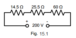
electrical circuit figure 15.1
A. 29 V
B. 14 V
C. 30.5 V
D. 18 V
Answer: Option A
Solution:
713. The circuit shown in Fig. 15.1 is called a series circuit because ________
electrical circuit figure 15.1
A. it contains a few resistances
B. it carries the same current throughout the circuit
C. it is a simple circuit
D. none of the above
Answer: Option B
Solution:
714. Referring to Fig. 15.2, the total circuit resistance will be _________
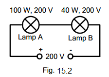
electrical circuit figure 15.2
A. 1000 ohms
B. 400 ohms
C. 1400 ohms
D. 135 ohms
Answer: Option C
Solution:
715. In Fig. 15.2 ____
electrical circuit figure 15.2
A. the lamp A will be brighter than lamp B
B. the lamp B will be brighter than lamp A
C. the two lamps will be equally bright
D. none of the above
Answer: Option B
Solution:
716. When a number of resistances are connected in parallel, the total resistance is _______
A. less than the smaller resistance
B. greater than the smaller resistance
C. between the smaller and greatest resistance
D. none of the above
Answer: Option A
Solution:
717. Two resistances of 6 ohms and 3 ohms are connected in parallel. The total resistance is ________
A. 9 ohms
B. 18 ohms
C. 0.5 ohm
D. 2 ohms
Answer: Option D
Solution:
718. The value of R that will give a total resistance of 1.5 ohms in Fig. 15.3 is ____
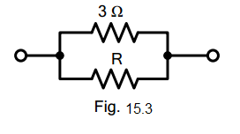
electrical circuit figure 15.3
A. 4 ohms
B. 6 ohms
C. 3 ohms
D. 9 ohms
Answer: Option C
Solution:
719. The current in 2.5 ohm resistor in Fig. 15.4 will be _________
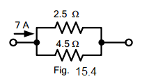
electrical circuit figure 15.4
A. 3 A
B. 4.5 A
C. 2.5 A
D. 2 A
Answer: Option B
Solution:
720. The current in 4.5 ohms resistor in Fig. 15.4 will be _________.
electrical circuit figure 15.4
A. 3.5 A
B. 3 A
C. 2 A
D. 2.5 A
Answer: Option D
Solution:
721. If 18 resistances, each of value 36 ohms, are connected in parallel, then the total resistance is _________
A. 2 ohms
B. 54 ohms
C. 36 ohms
D. none of the above
Answer: Option A
Solution:
722. Two incandescent lamps of 100 W, 200 V are in parallel across 200 V supply. The total resistance will be _______.
A. 800 ohms
B. 200 ohms
C. 400 ohms
D. 600 ohms
Answer: Option B
Solution:
723. The resistance across the terminals AB of the circuit shown in Fig. 15.5 is ________
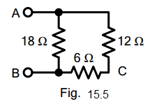
electrical circuit figure 15.5
A. 36 ohms
B. 18 ohms
C. 9 ohms
D. 15 ohms
Answer: Option C
Solution:
724. If a d.c. supply of 180 V is connected across terminals AB in Fig. 15.5, then current in 6 ohm resistor will be _________.
electrical circuit figure 15.5
A. 10 A
B. 5 A
C. 12 A
D. 6 A
Answer: Option A
Solution:
725. The resistance across terminals AC in Fig. 15.5 is ________
electrical circuit figure 15.5
A. 36 ohms
B. 9 ohms
C. 18 ohms
D. 8 ohms
Answer: Option D
Solution:
726. The resistance across terminals AB of the circuit shown in Fig. 15.6 is ________
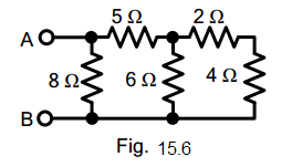
electrical circuit figure 15.6
A. 4 ohms
B. 18 ohms
C. 34 ohms
D. 8 ohms
Answer: Option A
Solution:
727. If a battery of 24 V is applied across terminals AB of the circuit shown in Fig. 15.6, then current in 2 ohm resistor will be ________
electrical circuit figure 15.6
A. 3 A
B. 6 A
C. 2.5 A
D. 1.5 A
Answer: Option D
Solution:
728. If a battery of 24 V is applied across terminals AB in Fig. 15.6, then power loss in 5 ohms resistor will be ________
electrical circuit figure 15.6
A. 180 W
B. 45 W
C. 90 W
D. 24 W
Answer: Option B
Solution:
729. The total conductance of the circuit shown in Fig. 15.7 is ________
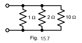
electrical circuit figure 15.7
A. 13 mhos
B. 1.6 mhos
C. 6 mhos
D. 2.5 mhos
Answer: Option B
Solution:
730. If 10 ohms resistance is removed in Fig. 15.7, then total conductance of the circuit will be ________
electrical circuit figure 15.7
A. 3 mhos
B. 6 mhos
C. 2 mhos
D. 1.5 mhos
Answer: Option D
Solution:
731. The voltage across the parallel circuit shown in Fig. 15.8 is ________
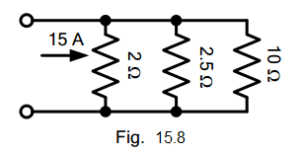
electrical circuit figure 15.8
A. 15 V
B. 10 V
C. 30 V
D. 12. 5 V
Answer: Option A
Solution:
732. The current in 10 ohms resistor in Fig. 15.8 is ________
electrical circuit figure 15.8
A. 3 A
B. 2.5 A
C. 1.5 A
D. 3.5 A
Answer: Option C
Solution:
733. The total resistance between terminals 1 and 2 of the circuit shown in Fig. 15.9 is _______
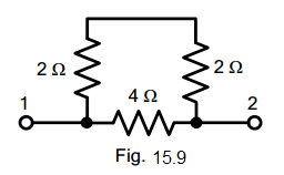
electrical circuit figure 15.9
A. 12 ohms
B. 2.67 ohms
C. 2 ohms
D. 64 ohms
Answer: Option C
Solution:
734. If a battery of 12 V is applied across terminals 1 and 2 of Fig. 15.9, then current through 4 ohms resistor will be ________
electrical circuit figure 15.9
A. 1.5 A
B. 3 A
C. 2 A
D. 2.5 A
Answer: Option B
Solution:
735. The resistance between terminals 1 and 2 of Fig. 15.10 is _________
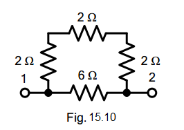
electrical circuit figure 15.10
A. 12 ohms
B. 8 ohms
C. 16 ohms
D. 3 ohms
Answer: Option C
Solution:
736. The resistance between terminals 1 and 2 in Fig. 15.11 is ________
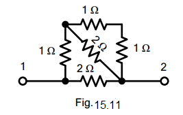
electrical circuit figure 15.11
A. 2 ohms
B. 1.5 ohms
C. 1 ohm
D. 4 ohms
Answer: Option C
Solution:
237. If a battery of 6 V is applied across terminals 1 and 2 in Fig. 15.11, then current in the horizontal 2 ohm resistor will be ________
electrical circuit figure 15.11
A. 1 A
B. 2 A
C. 3 A
D. 0.5 A
Answer: Option C
Solution:
738. The resistance across terminals 1 and 2 in Fig. 15.12 is _________
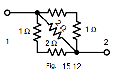
electrical circuit figure 15.12
A. 6 ohms
B. 12 ohms
C. 18 ohms
D. 24 ohms
Answer: Option A
Solution:
739. Two equal resistances are connected in series across a certain supply. If the resistances are now connected in parallel across the same supply, the power produced will be ________ that of series connection.
A. two times
B. four times
C. one-half
D. one-fourth
Answer: Option B
Solution:
740. Referring to Fig. 15.13, the resistance across terminals BE is ________
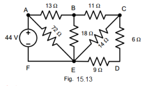
electrical circuit figure 15.13
A. 9 ohms
B. 18 ohms
C. 10 ohms
D. none of the above
Answer: Option A
Solution:
741. Referring to Fig. 15.13, the resistance across terminals AF is ________
electrical circuit figure 15.13
A. 20.5 ohms
B. 18 ohms
C. 11 ohms
D. none of the above
Answer: Option C
Solution:
742. Referring to Fig. 15.13, the current in 18 ohms resistor will be ________
electrical circuit figure 15.13
A. 2 A
B. 1.5 A
C. 1 A
D. none of the above
Answer: Option C
Solution:
743. Referring to Fig. 15.13, the power loss in 11 ohms will be ______
electrical circuit figure 15.13
A. 11 W
B. 24 W
C. 16 W
D. none of the above
Answer: Option A
Solution:
744. If in Fig. 15.14, switches S1 and S2 are closed, then total circuit resistance is _______
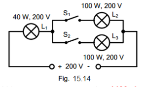
electrical circuit figure 15.14
A. 400 ohms
B. 1200 ohms
C. 1000 ohms
D. 2400 ohms
Answer: Option B
Solution:
745. If switch S1 is open and switch S2 is closed in Fig. 15.14, then circuit resistance will be _________
electrical circuit figure 15.14
A. 1200 ohms
B. 1000 ohms
C. 1400 ohms
D. 2400 ohms
Answer: Option C
Solution:
746. If in Fig. 15.14, both switches S1 and S2 are closed, then ________
electrical circuit figure 15.14
A. L1 will be brighter than L2 or L3
B. L1 will be dimmer than L2 or L3
C. L1 will be as bright as L2 or L3
D. none of the above
Answer: Option A
Solution:
747. If in Fig. 15.14 switches S1 and S2 are open, then lamp L1 will give output _______
electrical circuit figure 15.14
A. less than 40 W
B. more than 40 W
C. equal to 40 W
D. none of the above
Answer: Option D
Solution:
748. If in Fig. 15.14 switches S1 and S2 are closed and the supply voltage is increased to 400 V, then ________
electrical circuit figure 15.14
A. lamp L1 will burn out
B. lamp L2 will burn out
C. both lamps L2 and L3 will burn out
D. all the lamps will be safe
Answer: Option A
Solution:
749. If in Fig. 15.15, resistor R2 becomes open-circuited, the reading of the voltmeter will become
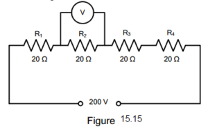
electrical circuit figure 15.15
A. zero
B. 150 V
C. 50 V
D. 200 V
Answer: Option D
Solution:
750. Whatever the battery voltage in Fig. 15.16, it is certain that smallest current will flow in the resistance of ______ ohm.
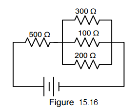
electrical circuit figure 15.16
A. 300
B. 500
C. 200
D. 100
Answer: Option A
Solution:
Questions and Answers in Electrical Circuit
Following is the list of practice exam test questions in this brand new series:
Complete List of MCQ in Electronics Engineering per topic
Related Content


P inoyBIX educates thousands of reviewers and students a day in preparation for their board examinations. Also provides professionals with materials for their lectures and practice exams. Help me go forward with the same spirit.
“Will you subscribe today via YOUTUBE?”
TIRED OF ADS?
- Become Premium Member and experienced complete ads-free content browsing.
- Full Content Access to Premium Solutions Exclusive for Premium members
- Access to PINOYBIX FREEBIES folder
- Download Reviewers and Learning Materials Free
- Download Content: You can see download/print button at the bottom of each post.
PINOYBIX FREEBIES FOR PREMIUM MEMBERSHIP:
- CIVIL ENGINEERING REVIEWER
- CIVIL SERVICE EXAM REVIEWER
- CRIMINOLOGY REVIEWER
- ELECTRONICS ENGINEERING REVIEWER (ECE/ECT)
- ELECTRICAL ENGINEERING & RME REVIEWER
- FIRE OFFICER EXAMINATION REVIEWER
- LET REVIEWER
- MASTER PLUMBER REVIEWER
- MECHANICAL ENGINEERING REVIEWER
- NAPOLCOM REVIEWER
- Additional upload reviewers and learning materials are also FREE
FOR A LIMITED TIME
If you subscribe for PREMIUM today!
You will receive an additional 1 month of Premium Membership FREE.
For Bronze Membership an additional 2 months of Premium Membership FREE.
For Silver Membership an additional 3 months of Premium Membership FREE.
For Gold Membership an additional 5 months of Premium Membership FREE.
Join the PinoyBIX community.