
A resistor behaves the same way no matter which direction current flows through it. A diode does not. Push current one way and it conducts almost freely. Push it the other way and it blocks almost everything. That one-way behavior is the entire reason diodes exist, and the ideal diode model is the simplest way engineers describe it before dealing with real-world complications. Every diode circuit you will ever analyze, from a simple rectifier to a voltage regulator, starts with this model.
This is Part 1 of the Semiconductor Diode Fundamentals ECE Board Exam Reviewer Series on PinoyBIX.org, the foundation series that comes before Diode Applications. If you already know rectifiers and clippers but skipped the basics, work through this one anyway — board examiners test the ideal-versus-practical distinction directly, and skipping it costs points. If you are reviewing for the ECE or EE board exam or currently enrolled in Electronics 1, save this page.
- ECE (Electronics Engineer) — The ideal and practical diode models appear in nearly every Electronic Devices and Circuits item as the first analysis step. Expect 3 to 5 items testing ON/OFF state determination, practical VF subtraction, and multi-diode series circuits. This is a prerequisite concept tested both directly and embedded inside rectifier, clipper, and clamper problems.
- EE (Electrical Engineer) — Appears in Electronics Engineering fundamentals, mostly as conceptual items confirming you understand forward and reverse bias behavior and can identify which model a problem calls for. Moderate frequency.
Bottom line: ECE examinees must master both models cold, know all three material-specific VF values, and be able to determine diode states in multi-diode circuits without hesitation. EE examinees must understand the concept and identify which model applies.
What Is a Diode? Understanding the Nonlinear Element
A diode is a two-terminal semiconductor device that conducts current easily in one direction and blocks it almost entirely in the other. That asymmetry breaks the straight-line behavior you know from resistors, which is why a diode is called a nonlinear circuit element. The terminal where conventional current enters during conduction is the anode. The terminal where it leaves is the cathode, usually marked with a stripe on the physical component. The diode symbol is an arrow pointing from anode to cathode, and that arrow shows the only direction current is allowed to flow when the diode is conducting.
The Diode as a Switch: Ideal Model Basics
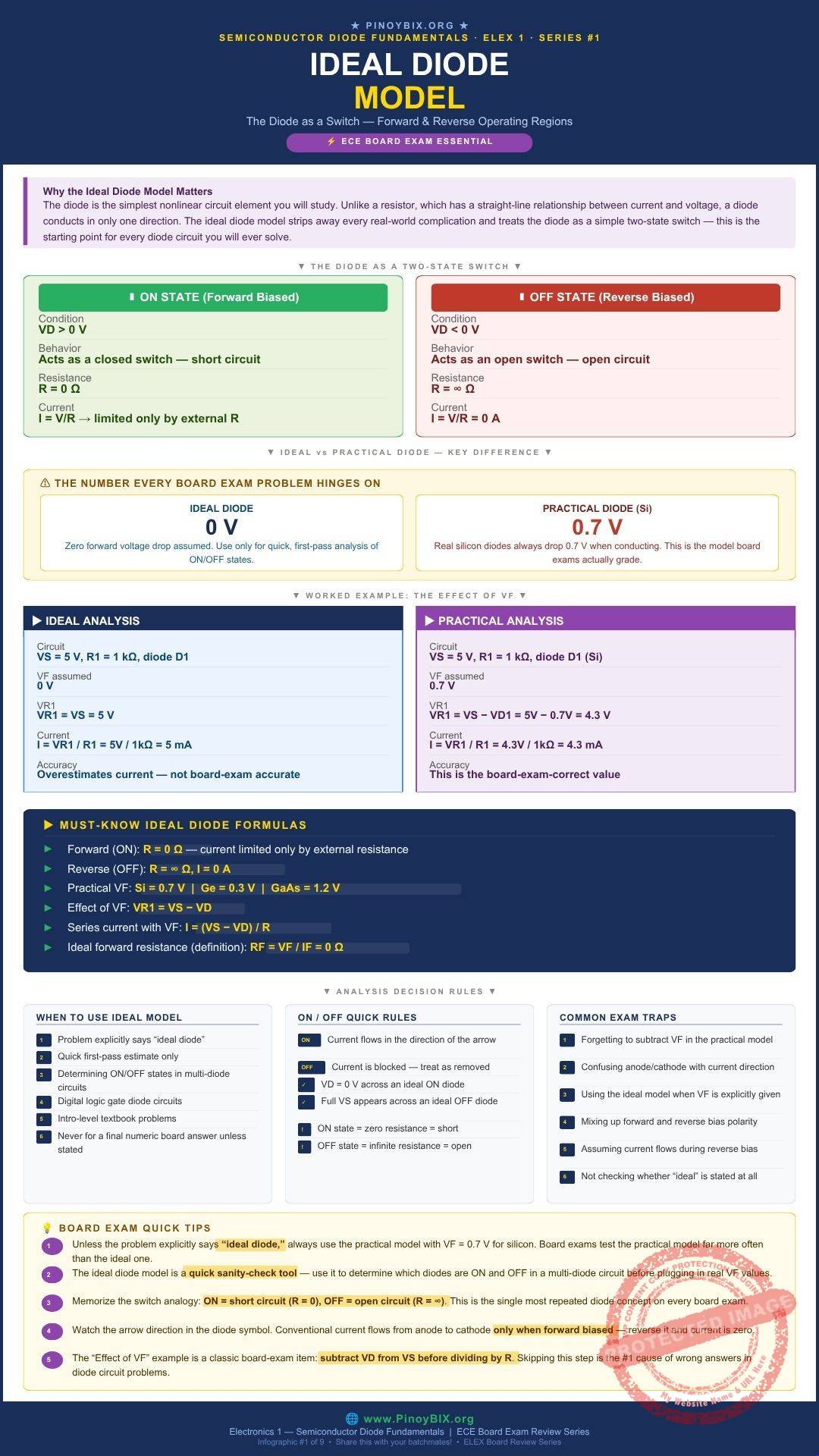
The ideal diode model reduces the diode to a two-state switch. In one state it closes completely, acting as a plain wire with zero resistance. In the other state it opens completely, acting as a break in the circuit with infinite resistance. There is no in-between and no voltage drop to account for. This makes the ideal model fast to apply, and at the same time, not fully accurate.
![\[R_{forward} = 0\ \Omega \qquad R_{reverse} = \infty\ \Omega, \quad I_{reverse} = 0\text{ A}\]](https://pinoybix.org/wp-content/ql-cache/quicklatex.com-aaa52c2fea60ba03e7d198c7f5036cca_l3.svg "Rendered by QuickLaTeX.com")
Forward biased current is limited only by whatever external resistance exists in the circuit.
Forward Bias and Reverse Bias in the Ideal Model
A diode is forward biased when the applied voltage pushes current in the direction the arrow points. Under the ideal model, forward bias means instant conduction — the diode becomes a short circuit and the full source voltage appears across whatever else is in the loop.
A diode is reverse biased when the applied voltage pushes against the arrow. Under the ideal model, reverse bias means instant blocking — the diode becomes an open circuit and the entire source voltage appears across the diode itself, with zero current flowing anywhere in that branch.
This ON or OFF determination is usually the first step in solving any diode circuit, ideal or practical. Get the direction wrong and every following calculation collapses, no matter how correct the arithmetic is.
Ideal vs Practical Diode: The VF Difference That Actually Matters
A real, practical diode does not drop 0 V when it conducts. It drops a fairly consistent forward voltage, called  , that depends on the semiconductor material. For silicon, the standard board exam value is
  . For germanium, it drops to
  . For gallium arsenide, it rises to
  .
.
![\[V_F(\text{Si}) = 0.7\text{ V} \qquad V_F(\text{Ge}) = 0.3\text{ V} \qquad V_F(\text{GaAs}) = 1.2\text{ V}\]](https://pinoybix.org/wp-content/ql-cache/quicklatex.com-a54a127930fbc4c168558929ec881d5c_l3.svg "Rendered by QuickLaTeX.com")
![\[V_{R1} = V_S - V_F\]](https://pinoybix.org/wp-content/ql-cache/quicklatex.com-013d21dc0c46bb008b676909e6bf6449_l3.svg "Rendered by QuickLaTeX.com")
Unless a board exam item explicitly states “assume an ideal diode,” default to the practical model. That single phrase changes your entire approach, and missing it is the most common way examinees lose points on this topic.
Worked Problems — Board Exam Type Questions
The following 10 problems are representative of actual ECE and EE board exam questions on the ideal and practical diode models. Work each problem by hand before reading the solution.
Problem 1 — ECE Board Exam Type
A single silicon diode is connected in series with a 6 V source, oriented so the source pushes current in the direction of the arrow. Assuming the ideal diode model, is the diode ON or OFF?
Given: Silicon diode, ideal model,  V, forward orientation
Find: ON or OFF state
Solution:
Step 1: The source pushes current in the direction the arrow allows, so the diode is forward biased.
Step 2: Under the ideal model, a forward biased diode is ON, behaving as a short circuit.
Examiner note: No calculation is needed here. Direction of bias alone answers the question.
Problem 2 — ECE Board Exam Type
A silicon diode ( V) is in series with
  and a 5 V source, using the practical model. Find the current through the circuit.
Given: Si diode, V, ,  V, practical model
Find: 
Solution:
Step 1: Subtract the diode drop from the source voltage.
![\[V_{R1} = V_S - V_F = 5 - 0.7 = 4.3 \text{ V}\]](https://pinoybix.org/wp-content/ql-cache/quicklatex.com-c526c288a1bcf935838282b79fd6b381_l3.svg "Rendered by QuickLaTeX.com")
Step 2: Divide by the resistance.
![\[I = \dfrac{V_{R1}}{R_1} = \dfrac{4.3}{1000} = 4.3 \text{ mA}\]](https://pinoybix.org/wp-content/ql-cache/quicklatex.com-526a7001cf6c655510bd39b23fd2245c_l3.svg "Rendered by QuickLaTeX.com")
 mA
mA
Examiner note: This is the single most repeated numeric setup on ECE board exams for this topic. Memorize the two-step process: subtract , then divide by  .
.
Problem 3 — ECE Board Exam Type
Repeat Problem 2, but replace the silicon diode with a germanium diode ( V).
V).
Given: Ge diode, V, , V
Find:
Solution:
Step 1:  V
V
Step 2:  mA
mA
 mA
mA
Examiner note: A lower always produces a higher current for the same source and resistor, since less voltage is used up by the diode itself.
Problem 4 — ECE Board Exam Type
Repeat Problem 2 once more, this time with a gallium arsenide diode ( V).
V).
Given: GaAs diode, V, , V
Find:
Solution:
Step 1:  V
V
Step 2:  mA
mA
 mA
mA
Examiner note: Compare Problems 2 through 4 side by side — same source, same resistor, three different currents, purely from . This is exactly the kind of comparison examiners build multiple-choice items around.
Problem 5 — ECE Board Exam Type
A silicon diode is connected so an 8 V source pushes current against the arrow. Using the ideal model, find the current through the circuit.
Given: Si diode, ideal model,  V, reverse orientation
Find:
Solution:
Step 1: The source opposes the arrow direction, so the diode is reverse biased.
Step 2: Under the ideal model, a reverse biased diode is an open circuit.
 A
A
Examiner note: The full 8 V appears across the diode terminals themselves in this case, not across any resistor in the loop.
Problem 6 — ECE Board Exam Type
Two identical silicon diodes are connected in series, both forward biased, with a 10 V source and  . Find the circuit current using the practical model.
Given: Two Si diodes in series,  V, , practical model
Find:
Solution:
Step 1: Total diode drop:  V
V
Step 2:  V, then
  mA
mA
mA
Examiner note: Every diode in a forward biased series path contributes its own . Forgetting the second diode’s drop is a common exam mistake.
Problem 7 — ECE Board Exam Type
A silicon diode is placed in series with a 0.5 V source and  , oriented for forward conduction. Is the diode ON or OFF under the practical model?
Given: Si diode,  V, , forward orientation, practical model
Find: ON or OFF state
Solution:
Step 1: Compare the source voltage to the silicon threshold:  .
.
Step 2: There is not enough potential to overcome the barrier, so the diode does not conduct.
A
Examiner note: Always compare the source voltage to before assuming a forward biased diode automatically conducts. This is a favorite trap in item construction.
Problem 8 — ECE Board Exam Type
A silicon diode,  , and a 10 V source are in series, forward biased. Find the voltage across
  and the current through the circuit.
Given: Si diode, , V, practical model
Find:  and
and
Solution:
Step 1:  V
V
Step 2:  mA
mA
 V,
V,  mA
mA
Examiner note: Round only at the final step, not in the middle of the calculation, to avoid compounding rounding error on multi-part items.
Problem 9 — ECE Board Exam Type
For the circuit in Problem 2 ( V, , silicon diode), find the percent difference between the ideal model current and the practical model current.
Given: Problem 2 circuit, both models
Find: Percent difference
Solution:
Step 1: Ideal current:  mA
mA
Step 2: Practical current from Problem 2:  mA
mA
![\[\dfrac{5 - 4.3}{4.3} \times 100\% \approx 16.3\%\]](https://pinoybix.org/wp-content/ql-cache/quicklatex.com-0079dae2bdb84f0811db13b1254ba450_l3.svg "Rendered by QuickLaTeX.com")
Examiner note: This is why the ideal model is reserved for quick estimates and ON/OFF logic, not for final numeric answers on the board exam.
Problem 10 — EE Board Exam Type
An EE board item asks for the practical difference between using the ideal versus practical diode model in circuit analysis. What is the best description?
Given: Conceptual comparison, ideal vs practical model
Find: Best description
Solution:
Step 1: The ideal model assumes 0 V drop and is used for fast ON/OFF determination.
Step 2: The practical model includes a material-dependent forward voltage and is used for accurate numeric analysis.
Examiner note: EE-level items usually stop at concept identification rather than requiring the full numeric derivation.
Common Mistakes and Examiner Traps
| ❌ Common Mistake | ✅ Correct Approach |
|---|---|
| Using the ideal model when is explicitly given |
Default to the practical model whenever a specific forward voltage or material is stated in the problem. |
| Forgetting to subtract before dividing by resistance |
Always subtract first — skipping this step overestimates current by roughly 15 to 20 percent. |
| Confusing anode and cathode direction | Trace the arrow from anode to cathode before deciding the bias condition. |
Not checking if  exceeds exceeds |
Compare the source voltage to the threshold before assuming a forward biased diode conducts. |
| Forgetting to add every diode’s drop in a multi-diode series path | Add for each conducting diode in the series path, not just one. |
| Assuming any conducting diode drops exactly 0 V | Remember this is only true under the ideal model, not the practical model used in most board items. |
Board Exam Quick Tips
- Read the problem statement for the word “ideal” before touching a single formula. That one word decides your entire approach.
- Default to the practical model with
 V for silicon unless told otherwise.
 - Always confirm the diode is actually forward biased before assuming it conducts. Direction first, math second.
- Check that
 exceeds
  before crediting a forward biased diode with conduction.
 - Subtract from before dividing by resistance — skipping this step is the most common source of wrong answers on this topic.
Frequently Asked Questions
Q1. Is the ideal diode model ever the correct choice on the board exam?
Yes, when the item explicitly says “ideal diode” or when you only need to determine ON/OFF states in a multi-diode logic circuit before running detailed numbers.
Q2. Why does silicon use 0.7 V specifically?
It is the standard threshold voltage required to overcome the potential barrier at a silicon PN junction at room temperature. Germanium and gallium arsenide have different band gaps, so their thresholds differ.
Q3. Does the forward voltage change with current?
Slightly, yes, in a real diode. For board exam purposes, is treated as a constant value regardless of current unless the problem states otherwise.
Q4. What happens if I use the wrong material’s value?
Your final numeric answer will not match the expected result even though your method is correct. Always confirm which material the problem specifies.
Q5. Why does the diode symbol point in only one direction?
The arrow shows the direction conventional current flows when the diode is forward biased and conducting. It always points from anode to cathode.
What Is Next
Now that you understand how a diode behaves as a switch, the next post steps back into the physics that makes this behavior possible in the first place — semiconductor materials and energy levels, and why silicon, germanium, and gallium arsenide sit exactly where they do on the conductivity spectrum.
→ Continue to Post 2 — Semiconductor Materials and Energy Levels
→ Back to the Semiconductor Diode Fundamentals Series Index
Published by PinoyBIX.org — Engineering Education for Every Filipino Student. Electronics · Mathematics · Board Exam Review · Free for Everyone.
Related Content


P inoyBIX educates thousands of reviewers and students a day in preparation for their board examinations. Also provides professionals with materials for their lectures and practice exams. Help me go forward with the same spirit.
“Will you subscribe today via YOUTUBE?”
TIRED OF ADS?
- Become Premium Member and experienced complete ads-free content browsing.
- Full Content Access to Premium Solutions Exclusive for Premium members
- Access to PINOYBIX FREEBIES folder
- Download Reviewers and Learning Materials Free
- Download Content: You can see download/print button at the bottom of each post.
PINOYBIX FREEBIES FOR PREMIUM MEMBERSHIP:
- CIVIL ENGINEERING REVIEWER
- CIVIL SERVICE EXAM REVIEWER
- CRIMINOLOGY REVIEWER
- ELECTRONICS ENGINEERING REVIEWER (ECE/ECT)
- ELECTRICAL ENGINEERING & RME REVIEWER
- FIRE OFFICER EXAMINATION REVIEWER
- LET REVIEWER
- MASTER PLUMBER REVIEWER
- MECHANICAL ENGINEERING REVIEWER
- NAPOLCOM REVIEWER
- Additional upload reviewers and learning materials are also FREE
FOR A LIMITED TIME
If you subscribe for PREMIUM today!
You will receive an additional 1 month of Premium Membership FREE.
For Bronze Membership an additional 2 months of Premium Membership FREE.
For Silver Membership an additional 3 months of Premium Membership FREE.
For Gold Membership an additional 5 months of Premium Membership FREE.
Join the PinoyBIX community.