
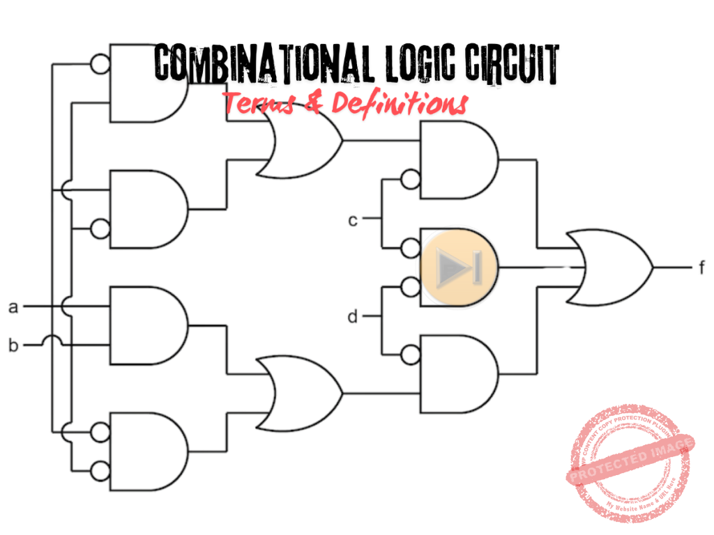
Are engineering board exams keeping you up at night? If you’re breaking into a cold sweat just thinking about combinational logic circuits, you’re not alone. Every year, thousands of engineering students struggle with these fundamental concepts that examiners love to test. Whether it’s trying to memorize Boolean laws the night before your exam or confusing a multiplexer with a demultiplexer during practice tests, the frustration is real.
I’ve been there too. During my own board exam preparation, I spent countless hours flipping through thick textbooks, desperately searching for clear explanations of digital logic concepts. That’s exactly why I created this comprehensive guide of 110+ combinational logic circuit terms.
This isn’t just another boring list of definitions. Each term is explained in plain language with just enough technical detail to help you truly understand the concept, not just memorize it. I’ve organized everything into logical sections based on my decade of engineering education experience and years of analyzing previous board exams.
Let’s face it—digital electronics can make or break your board exam score. The good news? Once you master these terms, you’ll approach those tricky combinational logic questions with confidence instead of confusion.
Basic Logic Concepts
1. Logic Gate: Electronic circuit that performs a logical operation on one or more binary inputs to produce a single binary output.
2. Boolean Algebra: Mathematical system used to describe and analyze digital circuits using binary variables and logical operations.
3. Truth Table: A table showing the output states of a logic circuit for all possible combinations of input states.
4. Binary Digit (Bit): The basic unit of information in digital systems, representing either a 0 or 1.
5. Boolean Variable: A variable that can assume only two discrete values: 0 (false) or 1 (true).
6. Boolean Expression: An algebraic expression that represents a logical function using Boolean variables.
7. Canonical Form: Standard way of expressing Boolean functions either as the sum of products (SOP) or product of sums (POS).
8. Logic Level: The voltage representing a logic 0 (LOW) or logic 1 (HIGH) in digital circuits.
9. Fan-out: Maximum number of digital inputs that a gate output can reliably drive.
10. Propagation Delay: Time required for a change in input to produce a corresponding change in output of a logic gate.
Fundamental Logic Gates
11. AND Gate: Logic gate that outputs 1 only when all inputs are 1.
12. OR Gate: Logic gate that outputs 1 when at least one input is 1.
13. NOT Gate: Logic gate that inverts the input signal, also called an inverter.
14. NAND Gate: Universal logic gate performing the NOT-AND operation, outputs 0 only when all inputs are 1.
15. NOR Gate: Universal logic gate performing the NOT-OR operation, outputs 1 only when all inputs are 0.
16. XOR Gate: Exclusive-OR gate that outputs 1 when inputs are different, 0 when inputs are the same.
17. XNOR Gate: Exclusive-NOR gate that outputs 1 when inputs are the same, 0 when inputs are different.
18. Buffer Gate: Gate that preserves its input while providing amplification or isolation.
19. Universal Gate: A gate like NAND or NOR that can implement any Boolean function without requiring other gate types.
20. Transmission Gate: Analog switch that can conduct in both directions or block signal flow based on a control input.
Boolean Laws and Theorems
21. Commutative Law: States that A + B = B + A and A · B = B · A.
22. Associative Law: States that (A + B) + C = A + (B + C) and (A · B) · C = A · (B · C).
23. Distributive Law: States that A · (B + C) = A · B + A · C and A + (B · C) = (A + B) · (A + C).
24. Identity Law: States that A + 0 = A and A · 1 = A.
25. Null Law: States that A + 1 = 1 and A · 0 = 0.
26. Idempotent Law: States that A + A = A and A · A = A.
27. Complement Law: States that A + A’ = 1 and A · A’ = 0.
28. Double Negation: States that (A’)’ = A.
29. De Morgan’s First Theorem: States that (A + B)’ = A’ · B’.
30. De Morgan’s Second Theorem: States that (A · B)’ = A’ + B’.
31. Absorption Law: States that A + (A · B) = A and A · (A + B) = A.
32. Consensus Theorem: States that (A · B) + (B · C) + (A’ · C) = (A · B) + (A’ · C).
Combinational Circuit Analysis and Design
33. Sum-of-Products (SOP): Boolean expression written as the OR of AND terms, representing minterms.
34. Product-of-Sums (POS): Boolean expression written as the AND of OR terms, representing maxterms.
35. Minterm: A product term in which all variables appear exactly once in either true or complemented form.
36. Maxterm: A sum term in which all variables appear exactly once in either true or complemented form.
37. Canonical SOP Form: Boolean expression written as the sum of all minterms for which the function equals 1.
38. Canonical POS Form: Boolean expression written as the product of all maxterms for which the function equals 0.
39. Don’t Care Condition: Input combination for which the output value is irrelevant, used for circuit simplification.
40. Boolean Function Minimization: Process of simplifying Boolean expressions to reduce gate count and implementation cost.
41. Karnaugh Map (K-map): Graphical method for simplifying Boolean expressions by grouping adjacent minterms.
42. Prime Implicant: A product term that cannot be combined with any other term to form a simpler term while covering the same minterms.
43. Essential Prime Implicant: A prime implicant that covers at least one minterm not covered by any other prime implicant.
44. Quine-McCluskey Method: Tabular method for minimizing Boolean functions, especially useful for functions with many variables.
45. Karnaugh Map Grouping: Process of identifying adjacent cells in a K-map to form larger groups of 2^n cells for simplification.
Standard Combinational Circuits
46. Half Adder: A Combinational circuit that adds two binary digits and produces sum and carry outputs.
47. Full Adder: A Combinational circuit that adds three binary digits (two inputs plus a carry-in) and produces sum and carry outputs.
48. Ripple Carry Adder: Multiple full adders connected in series with carry propagating from one stage to the next.
49. Carry Look-ahead Adder: A high-speed adder that pre-calculates carry signals to reduce propagation delay.
50. Binary Subtractor: A Circuit that performs subtraction of binary numbers using 2’s complement representation.
51. Half Subtractor: A Combinational circuit that subtracts two binary digits and produces difference and borrow outputs.
52. Full Subtractor: A Combinational circuit that subtracts two binary digits with a borrow-in and produces difference and borrow outputs.
53. Multiplexer (MUX): Circuit that selects one of several input signals and forwards it to a single output based on control signals.
54. Demultiplexer (DEMUX): Circuit that routes a single input to one of several outputs based on control signals.
55. Encoder: A Combinational circuit that converts multiple input lines into a coded binary output.
56. Decoder: A Combinational circuit that converts a binary code input into one of 2^n output lines.
57. Priority Encoder: An Encoder that handles multiple active inputs by selecting the input with the highest priority.
58. Binary-to-Gray Code Converter: A Circuit that converts binary code to Gray code, where adjacent numbers differ by only one bit.
59. Gray-to-Binary Code Converter: Circuit that converts Gray code back to binary code.
60. Parity Generator: A Circuit that produces a parity bit for error detection purposes.
61. Parity Checker: A Circuit that verifies if the received data has the correct parity bit.
62. Magnitude Comparator: A Circuit that compares two binary numbers and determines their relationship (equal, greater than, less than).
63. Binary Parallel Adder: A Circuit that adds multiple bits simultaneously using several full adders.
64. BCD Adder: Circuit specifically designed to add binary-coded decimal digits.
Integrated Circuit Technologies
65. TTL (Transistor-Transistor Logic): Family of digital ICs using bipolar transistors with multiple emitters.
66. CMOS (Complementary Metal-Oxide-Semiconductor): Low-power IC technology using complementary pairs of MOSFETs.
67. ECL (Emitter-Coupled Logic): High-speed bipolar IC technology with transistors operated in non-saturating mode.
68. BiCMOS: Integrated circuit technology that combines bipolar and CMOS transistors.
69. Open-Collector Output: Output configuration that can be wired with other outputs to implement certain logic functions.
70. Tri-state Output: Output that can be in high, low, or high-impedance (disconnected) state.
71. Pull-up Resistor: Resistor connected between signal line and positive supply to ensure a defined logic level when outputs are inactive.
72. Current Sinking: Capability of a logic gate to draw current from connected loads when the output is LOW.
73. Current Sourcing: Capability of a logic gate to supply current to connected loads when the output is HIGH.
74. Noise Margin: Maximum noise voltage that can be added to an input signal without causing an undesired output change.
Advanced Combinational Circuits
75. Arithmetic Logic Unit (ALU): A Combinational circuit that performs arithmetic and logical operations.
76. Barrel Shifter: A Combinational circuit that can shift or rotate data by a specified number of bits in a single operation.
77. Multiplier Circuit: A Combinational circuit that performs binary multiplication.
78. Array Multiplier: Multiplication circuit implemented using an array of AND gates and adders.
79. Wallace Tree Multiplier: Fast multiplication circuit using carry-save adders arranged in a tree structure.
80. Booth Multiplier: An Efficient multiplication algorithm that handles signed numbers.
81. Divider Circuit: A Combinational circuit that performs binary division.
82. Carry Select Adder: A Fast adder that pre-computes sum values for possible carry inputs.
83. Carry Skip Adder: Adder designed to reduce carry propagation time by skipping over groups of consecutive stages.
84. Carry Save Adder: An Adder used in multi-operand addition that processes carries separately from sums.
85. BCD-to-Seven-Segment Decoder: Circuit that converts BCD input to outputs for driving a seven-segment display.
86. Code Converter: Circuit that transforms one coding scheme into another (e.g., BCD to Excess-3).
87. Data Selector: Another term for multiplexer, selecting one of multiple data inputs based on selection lines.
88. Binary Rate Multiplier: Circuit that generates a pulse stream with frequency proportional to a binary input value.
Circuit Performance and Analysis
89. Noise Immunity: Ability of a digital circuit to tolerate noise without producing incorrect outputs.
90. Power Dissipation: Energy consumed by a logic gate or circuit, often expressed in milliwatts.
91. Rise Time: Time required for a signal to change from 10% to 90% of its final value.
92. Fall Time: Time required for a signal to change from 90% to 10% of its initial value.
93. Setup Time: Minimum time before clock edge that input must be stable for reliable operation.
94. Hold Time: Minimum time after clock edge that input must remain stable.
95. Glitch: Unwanted transient output from a combinational circuit due to unequal propagation delays.
96. Hazard: Potential temporary output error in combinational circuits during input transitions.
97. Static Hazard: Single variable change causing unwanted output transition.
98. Dynamic Hazard: Multiple output transitions occurring when only one transition should occur.
99. Race Condition: A Timing problem where the output depends on which input signal arrives first.
100. Critical Path: Longest signal propagation path through a circuit, determining maximum operating frequency.
101. Logic Threshold: Voltage level that separates the logic 0 and logic 1 regions.
102. Logic Family: A Group of integrated circuits with compatible voltage levels and interface characteristics.
103. Gate Equivalence: Number of basic gates (typically NAND gates) required to implement a function.
104. Switching Function: A Mathematical function that describes the behavior of a digital circuit.
105. Shannon’s Expansion Theorem: Method for decomposing Boolean functions by cofactors.
106. Boolean Difference: Used to determine the effect of a variable on a switching function.
107. Reed-Muller Expansion: Alternative canonical form for representing Boolean functions.
108. XOR Canonical Form: Boolean expression written as the XOR of product terms.
109. Function Realization: Implementation of a Boolean function using available gate types.
110. Logic Optimization: The Process of finding the most efficient implementation of a logic function.
Mastering these 101+ combinational logic circuit terms won’t happen overnight, but consistent study will transform these concepts from confusing jargon into tools you can confidently apply in your board exams.
Remember when digital electronics seemed like an impossible mountain to climb? Look how far you’ve come. Keep this guide bookmarked and return to it regularly as your exam approaches. Many successful engineers tell me this systematic approach to learning combinational logic made all the difference in their exam performance.
Still struggling with particular concepts? Drop a comment below with your specific questions. Our community of engineering students and professionals is here to help each other succeed. Also, don’t forget to download the printable PDF version of this guide for your late-night study sessions.
The path to passing your board exam isn’t about memorizing everything—it’s about understanding the fundamental concepts that examiners repeatedly test. These combinational logic circuit terms represent exactly that kind of high-value knowledge.
Study smart, practice consistently, and approach your exam with confidence. I’ll be rooting for you on exam day!
Related Content


P inoyBIX educates thousands of reviewers and students a day in preparation for their board examinations. Also provides professionals with materials for their lectures and practice exams. Help me go forward with the same spirit.
“Will you subscribe today via YOUTUBE?”
TIRED OF ADS?
- Become Premium Member and experienced complete ads-free content browsing.
- Full Content Access to Premium Solutions Exclusive for Premium members
- Access to PINOYBIX FREEBIES folder
- Download Reviewers and Learning Materials Free
- Download Content: You can see download/print button at the bottom of each post.
PINOYBIX FREEBIES FOR PREMIUM MEMBERSHIP:
- CIVIL ENGINEERING REVIEWER
- CIVIL SERVICE EXAM REVIEWER
- CRIMINOLOGY REVIEWER
- ELECTRONICS ENGINEERING REVIEWER (ECE/ECT)
- ELECTRICAL ENGINEERING & RME REVIEWER
- FIRE OFFICER EXAMINATION REVIEWER
- LET REVIEWER
- MASTER PLUMBER REVIEWER
- MECHANICAL ENGINEERING REVIEWER
- NAPOLCOM REVIEWER
- Additional upload reviewers and learning materials are also FREE
FOR A LIMITED TIME
If you subscribe for PREMIUM today!
You will receive an additional 1 month of Premium Membership FREE.
For Bronze Membership an additional 2 months of Premium Membership FREE.
For Silver Membership an additional 3 months of Premium Membership FREE.
For Gold Membership an additional 5 months of Premium Membership FREE.
Join the PinoyBIX community.