
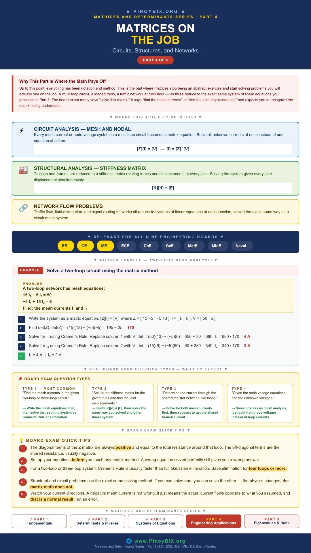
You already know how to multiply matrices, evaluate determinants, invert a matrix, and solve a linear system. Now comes the part that actually shows up on your board exam scoresheet. Every three-mesh circuit problem, every truss joint calculation, every mass balance across a mixing stream — they are all the same thing wearing different clothes. They are linear systems, and you solve them with the matrix tools from Parts 1, 2, and 3. This post covers matrices in engineering applications for the ECE, EE, CE, ME, and ChE board exam with 10 fully worked problems pulled from circuit analysis, structural engineering, and mass balance. This is Part 4 of the Matrices and Determinants Series.
- ECE (Electronics Engineer) — High frequency. Mesh analysis and nodal analysis of circuits with two or three loops appear regularly. Setting up
![[Z][I]=[V]](https://pinoybix.org/wp-content/ql-cache/quicklatex.com-7ca5d5c0d39072704ad53bec1e9be25b_l3.png "Rendered by QuickLaTeX.com") from a circuit diagram is a required skill.
from a circuit diagram is a required skill. - EE (Electrical Engineer) — Very high frequency. Three-mesh circuit problems with mutual impedance are a staple of the board exam. Network analysis by matrix methods is central to the Electrical Circuits subject.
- ME (Mechanical Engineer) — High frequency. Force equilibrium at joints, support reactions, and cable tension problems produce
 and
and  linear systems.
 - CE (Civil Engineer) — High frequency. Truss analysis by method of joints, reaction forces at supports, and moment equilibrium all produce simultaneous equations solved by matrices.
- ChE (Chemical Engineer) — Moderate to high frequency. Multi-stream mixing problems, reactor material balances, and distillation column problems produce matrix systems.
- GeE (Geodetic Engineer) — Moderate frequency. Coordinate transformation and least squares adjustment of survey measurements.
- MetE and MinE — Low to moderate frequency. Phase equilibrium and mass balance problems in Engineering Mathematics.
- Naval Architect and Marine Engineer — Moderate frequency. Hydrostatic force distribution and structural load problems.
Bottom line: ECE and EE examinees will meet mesh and nodal circuit problems on almost every full-length practice exam — that is your highest-value application here. CE and ME examinees should walk in ready to set up truss and beam equilibrium as a matrix system without hesitation. ChE examinees need the mass balance pattern down cold, since it is the one application type most other boards never see. The computation method is always the same across all of them — only the physical context changes.
The Universal Setup: ![[A][X] = [B]](https://pinoybix.org/wp-content/ql-cache/quicklatex.com-3073c749eabbdb852cd2ec90093d3d65_l3.png "Rendered by QuickLaTeX.com")
Every matrix application problem reduces to the same three steps. Master these three steps and you can handle any application problem regardless of the engineering discipline.
Step 1: Write one equation per unknown. Label your unknowns clearly before writing any equation.
Step 2: Arrange the equations in matrix form. Coefficients of each unknown go into matrix ![[A]](https://pinoybix.org/wp-content/ql-cache/quicklatex.com-b2e794eaaca376db17f79ff4fb8089b8_l3.png "Rendered by QuickLaTeX.com") . The unknowns form column vector
. The unknowns form column vector ![[X]](https://pinoybix.org/wp-content/ql-cache/quicklatex.com-0934d16fbd1e324d448f73ef07c2a631_l3.png "Rendered by QuickLaTeX.com") . The constants on the right-hand side form column vector
. The constants on the right-hand side form column vector ![[B]](https://pinoybix.org/wp-content/ql-cache/quicklatex.com-28b42a6e6a2c07f3ed58ce87b6856f18_l3.png "Rendered by QuickLaTeX.com") .
.
Step 3: Compute  . If it is nonzero, solve using Cramer’s rule or
 ![[X] = [A]^{-1}[B]](https://pinoybix.org/wp-content/ql-cache/quicklatex.com-cdc171330b0981da90366d00561472bf_l3.png "Rendered by QuickLaTeX.com") . If it is zero, use Gaussian elimination to determine whether the system is inconsistent or dependent.
. If it is zero, use Gaussian elimination to determine whether the system is inconsistent or dependent.
![\[[A][X] = [B] \qquad [X] = [A]^{-1}[B] \quad \text{when } \det(A) \neq 0\]](https://pinoybix.org/wp-content/ql-cache/quicklatex.com-3de9b6e7673130a92640c012261a2831_l3.png "Rendered by QuickLaTeX.com")
Whether is called an impedance matrix, an admittance matrix, a stiffness matrix, or a mass balance coefficient matrix, the structure is identical every time. Solve it the same way every time.
Application 1 — Mesh Current Analysis (ECE and EE)
Mesh analysis applies Kirchhoff’s Voltage Law (KVL) around each independent mesh of a circuit. Each mesh produces one equation. The unknowns are the mesh currents  . The result is a system
 ![[Z][I] = [V]](https://pinoybix.org/wp-content/ql-cache/quicklatex.com-f71433ebb019d0aa278805dbd62c6d2d_l3.png "Rendered by QuickLaTeX.com") , where
, where ![[Z]](https://pinoybix.org/wp-content/ql-cache/quicklatex.com-a622cc6057c3a322f7552a230a4ba025_l3.png "Rendered by QuickLaTeX.com") is the impedance matrix.
is the impedance matrix.
Diagonal entry  : sum of all impedances in mesh
  .
.
Off-diagonal entry  (for
(for  ): negative of the impedance shared between mesh and mesh
  .
.
Source entry  : algebraic sum of voltage sources in mesh (positive if the source drives current in the assumed mesh direction).
![\[[Z][I] = [V] \qquad [I] = [Z]^{-1}[V]\]](https://pinoybix.org/wp-content/ql-cache/quicklatex.com-931e85460b6068d8b897714f1c866579_l3.png "Rendered by QuickLaTeX.com")
The impedance matrix is always symmetric for passive circuits ( ). This symmetry is a useful check — if your off-diagonal entries are not equal in magnitude, recheck your KVL equations.
Application 2 — Nodal Voltage Analysis (ECE and EE)
Nodal analysis applies Kirchhoff’s Current Law (KCL) at each independent node. The unknowns are the node voltages  measured with respect to a reference node (ground). The result is
 ![[G][V] = [I]](https://pinoybix.org/wp-content/ql-cache/quicklatex.com-5ccb3b4441807dee3b351e34992c53fc_l3.png "Rendered by QuickLaTeX.com") , where
, where ![[G]](https://pinoybix.org/wp-content/ql-cache/quicklatex.com-d8c64214276070ebcb73f598790ba57b_l3.png "Rendered by QuickLaTeX.com") is the conductance matrix.
is the conductance matrix.
Diagonal entry  : sum of all conductances connected to node . (Conductance
  for resistors.)
Off-diagonal entry  (for ): negative of the conductance connected directly between node and node .
![\[[G][V] = [I_{source}]\]](https://pinoybix.org/wp-content/ql-cache/quicklatex.com-1a4833e728a28bd6ddf2d18d76d4d11d_l3.png "Rendered by QuickLaTeX.com")
Application 3 — Structural Force Systems (CE and ME)
Equilibrium problems at joints and supports produce simultaneous equations from the force balance conditions  ,
,  , and
, and  . The unknowns are the reaction forces or member forces.
![\[\sum F_x = 0: \quad F_1\cos\theta_1 + F_2\cos\theta_2 = P_x \qquad \sum F_y = 0: \quad F_1\sin\theta_1 + F_2\sin\theta_2 = P_y\]](https://pinoybix.org/wp-content/ql-cache/quicklatex.com-b8d1089b47f6451fd15e4f5507827414_l3.png "Rendered by QuickLaTeX.com")
In matrix form:
![\[\begin{bmatrix} \cos\theta_1 & \cos\theta_2 \\ \sin\theta_1 & \sin\theta_2 \end{bmatrix} \begin{bmatrix} F_1 \\ F_2 \end{bmatrix} = \begin{bmatrix} P_x \\ P_y \end{bmatrix}\]](https://pinoybix.org/wp-content/ql-cache/quicklatex.com-7033b23fdb368ac21d51252939f69d00_l3.png "Rendered by QuickLaTeX.com")
A second, related structural application solves for joint displacements instead of member forces, using the global stiffness matrix ![[K]](https://pinoybix.org/wp-content/ql-cache/quicklatex.com-2807673a459ac7b960b877427035ed1e_l3.png "Rendered by QuickLaTeX.com") :
:
![\[[K]\{d\} = \{F\}\]](https://pinoybix.org/wp-content/ql-cache/quicklatex.com-f56b12d4885904efab92a61a2afdc9a9_l3.png "Rendered by QuickLaTeX.com")
is the global stiffness matrix,  is the displacement vector at each free degree of freedom, and
  is the applied force vector. Fixed supports have zero displacement — remove those rows and columns from before solving.
Application 4 — Mass Balance Systems (ChE)
Steady-state mass balances at each mixing node give: input streams equal output streams for each component. With  unknown flow rates, you need independent balance equations — the overall balance plus
  component balances.
Overall balance:  Component balance:
![\[\begin{bmatrix} 1 & 1 \\ x_1 & x_2 \end{bmatrix} \begin{bmatrix} F_1 \\ F_2 \end{bmatrix} = \begin{bmatrix} F_3 \\ x_3 F_3 \end{bmatrix}\]](https://pinoybix.org/wp-content/ql-cache/quicklatex.com-184339894e1a2f10d3a95e87a9a5d229_l3.png "Rendered by QuickLaTeX.com")
10 Worked Board Exam Problems
Problem 1. Two-mesh circuit — setup and solve.
Given: Mesh 1 contains  ,
,  (shared), and
  V. Mesh 2 contains the shared ,
  , and
, and  V opposing the assumed direction.
Find: mesh currents  and
and 
Solution:
Step 1: Apply KVL to each mesh.
![\[\text{Mesh 1: } (R_1+R_2)I_1 - R_2I_2 = V_1 \implies 6I_1 - 2I_2 = 20\]](https://pinoybix.org/wp-content/ql-cache/quicklatex.com-59c8bd93d0a149daa6e150aa62b7132e_l3.png "Rendered by QuickLaTeX.com")
![\[\text{Mesh 2: } -R_2I_1 + (R_2+R_3)I_2 = -V_2 \implies -2I_1 + 8I_2 = -10\]](https://pinoybix.org/wp-content/ql-cache/quicklatex.com-8b8eda0410db73f59a1b4028f5ce31ee_l3.png "Rendered by QuickLaTeX.com")
Step 2: Write the matrix equation and compute  .
.
![\[[Z] = \begin{bmatrix}6&-2\\-2&8\end{bmatrix} \qquad \det Z = (6)(8)-(-2)(-2) = 48-4 = 44\]](https://pinoybix.org/wp-content/ql-cache/quicklatex.com-4b699e219e953508b354a38cfeac3d76_l3.png "Rendered by QuickLaTeX.com")
Step 3: Apply Cramer’s rule.
![\[I_1 = \dfrac{(20)(8)-(-2)(-10)}{44} = \dfrac{140}{44} = \dfrac{35}{11}\,\text{A} \qquad I_2 = \dfrac{(6)(-10)-(20)(-2)}{44} = \dfrac{-20}{44} = -\dfrac{5}{11}\,\text{A}\]](https://pinoybix.org/wp-content/ql-cache/quicklatex.com-0c88f9a7de965d7138c20725f2fe1048_l3.png "Rendered by QuickLaTeX.com")
 A,
A,  A
A
Examiner note: The negative sign on means the actual current flows opposite to the assumed mesh direction. This is a valid result, not an error — do not discard it. On the board exam, watch for a follow-up question asking which direction actually flows.
Problem 2. Three-mesh circuit — determine if a unique solution exists.
Given:  ,
,  ,
, 
Find:  and state whether a unique solution exists
Solution:
Step 1: Write the impedance matrix.
![\[Z = \begin{bmatrix}10&-2&0\\-2&8&-4\\0&-4&6\end{bmatrix}\]](https://pinoybix.org/wp-content/ql-cache/quicklatex.com-b7f89f8b9ecd84cc856ea5691929a8cd_l3.png "Rendered by QuickLaTeX.com")
Step 2: Expand along row 1. The zero in position  eliminates one term.
![\[\det Z = 10\begin{vmatrix}8&-4\\-4&6\end{vmatrix} - (-2)\begin{vmatrix}-2&-4\\0&6\end{vmatrix} + 0\]](https://pinoybix.org/wp-content/ql-cache/quicklatex.com-15bdff44648ba31aa519bc99c764fe54_l3.png "Rendered by QuickLaTeX.com")
Step 3: Compute the two remaining determinants and combine.
![\[= 10[48-16] + 2[-12-0] = 10(32) + 2(-12) = 320-24 = 296\]](https://pinoybix.org/wp-content/ql-cache/quicklatex.com-af5c6abb149943649dda615fb0522f91_l3.png "Rendered by QuickLaTeX.com")
 — a unique solution exists for all three mesh currents.
Examiner note: Expanding along the row with a zero reduced this from three determinants down to two. Always scan for zeros in an impedance matrix before you pick a row or column to expand along.
Problem 3. Two-node nodal analysis.
Given: conductance matrix equation 
Find:  and
and 
Solution:
Step 1: Compute  .
.
![\[\det G = (0.5)(0.7)-(-0.2)(-0.2) = 0.35-0.04 = 0.31\]](https://pinoybix.org/wp-content/ql-cache/quicklatex.com-3fb1456bc530c03b52e5d8197254d127_l3.png "Rendered by QuickLaTeX.com")
Step 2: Apply the inverse formula.
![\[G^{-1} = \dfrac{1}{0.31}\begin{bmatrix}0.7&0.2\\0.2&0.5\end{bmatrix}\]](https://pinoybix.org/wp-content/ql-cache/quicklatex.com-612ab3cf9de040c53f1539ec317cf978_l3.png "Rendered by QuickLaTeX.com")
Step 3: Multiply ![[V] = [G]^{-1}[I]](https://pinoybix.org/wp-content/ql-cache/quicklatex.com-18975be31e58b76b1456a8ed44daeb1e_l3.png "Rendered by QuickLaTeX.com") .
.
![\[V_1 = \dfrac{(0.7)(3)+(0.2)(5)}{0.31} = \dfrac{3.1}{0.31} = 10\,\text{V} \qquad V_2 = \dfrac{(0.2)(3)+(0.5)(5)}{0.31} = \dfrac{3.1}{0.31} = 10\,\text{V}\]](https://pinoybix.org/wp-content/ql-cache/quicklatex.com-3a950cd2dc5f529aa038682139f6fe98_l3.png "Rendered by QuickLaTeX.com")
 V, V
V, V
Examiner note: Equal node voltages mean no current flows through the branch connecting the two nodes. That is a physical sanity check, not a coincidence — if a result like this makes no sense electrically, your setup is wrong, not the computation.
Problem 4. Truss joint — two member forces.
Given: at a joint, two members make angles  and
and  with the horizontal. An external load of
  N and
N and  N acts at the joint.
Find: member forces  and
and 
Solution:
Step 1: Write the equilibrium equations in matrix form.
![\[\begin{bmatrix}\cos 30°&\cos 60°\\\sin 30°&\sin 60°\end{bmatrix}\begin{bmatrix}F_1\\F_2\end{bmatrix} = \begin{bmatrix}0\\1000\end{bmatrix} = \begin{bmatrix}\frac{\sqrt3}{2}&\frac12\\\frac12&\frac{\sqrt3}{2}\end{bmatrix}\begin{bmatrix}F_1\\F_2\end{bmatrix} = \begin{bmatrix}0\\1000\end{bmatrix}\]](https://pinoybix.org/wp-content/ql-cache/quicklatex.com-8b2ad39dddeafc1562a45f4df598cf7b_l3.png "Rendered by QuickLaTeX.com")
Step 2: Compute the determinant.
![\[\det A = \left(\dfrac{\sqrt3}{2}\right)\left(\dfrac{\sqrt3}{2}\right) - \left(\dfrac12\right)\left(\dfrac12\right) = \dfrac34-\dfrac14 = \dfrac12\]](https://pinoybix.org/wp-content/ql-cache/quicklatex.com-fc2f4aa7b64797ce7dfa0ad1b4b2c79f_l3.png "Rendered by QuickLaTeX.com")
Step 3: Apply Cramer’s rule.
![\[F_1 = \dfrac{0-500}{1/2} = -1000\,\text{N} \qquad F_2 = \dfrac{1000\sqrt3/2 - 0}{1/2} = 1000\sqrt3 \approx 1732\,\text{N}\]](https://pinoybix.org/wp-content/ql-cache/quicklatex.com-64bdaef74ae23137b1ccb3279b28512e_l3.png "Rendered by QuickLaTeX.com")
 N (compression),
  N (tension)
Examiner note: Negative force means the member is in compression — it pushes rather than pulls. State your sign convention clearly in your solution, or the examiner cannot tell whether your negative sign means compression or an error.
Problem 5. Beam support reactions.
Given: a simply supported beam, span  m, carries a central load
  kN and an eccentric load
  kN at the quarter point.
Find: support reactions  and
and 
Solution:
Step 1: Write the two equilibrium equations.
![\[\sum F_y = 0: \quad R_A + R_B = P+Q = 8\,\text{kN}\]](https://pinoybix.org/wp-content/ql-cache/quicklatex.com-5a0b6928c25ca30ebe15c02c3e4d09b7_l3.png "Rendered by QuickLaTeX.com")
![\[\sum M_A = 0: \quad R_B(8) = P(4)+Q(2) = 20+6 = 26\]](https://pinoybix.org/wp-content/ql-cache/quicklatex.com-41cf4b7877afbf111f5dbf386b912aee_l3.png "Rendered by QuickLaTeX.com")
Step 2: Write the matrix form and compute the determinant.
![\[\begin{bmatrix}1&1\\0&8\end{bmatrix}\begin{bmatrix}R_A\\R_B\end{bmatrix} = \begin{bmatrix}8\\26\end{bmatrix} \qquad \det = (1)(8)-(1)(0) = 8\]](https://pinoybix.org/wp-content/ql-cache/quicklatex.com-d893a65f2006fef2754f43146cb05b88_l3.png "Rendered by QuickLaTeX.com")
Step 3: Solve.
![\[R_B = \dfrac{26}{8} = 3.25\,\text{kN} \qquad R_A = \dfrac{64-26}{8} = \dfrac{38}{8} = 4.75\,\text{kN}\]](https://pinoybix.org/wp-content/ql-cache/quicklatex.com-a241830fc48be94ae87800899a7b5686_l3.png "Rendered by QuickLaTeX.com")
 kN,
kN,  kN
kN
Examiner note: Verify:  kN ✓. Taking moments about A eliminated from that equation immediately, which is often faster than a full Cramer’s rule setup. Look for a simpler physical shortcut before defaulting to the full matrix method.
Problem 6. Mass balance — two-stream mixing.
Given: stream 1 has mass fraction  , stream 2 has
  . The product stream has
  and total flow
  kg/hr.
Find: and
Solution:
Step 1: Write the overall and component balances.
![\[F_1+F_2 = 100 \qquad 0.3F_1+0.7F_2 = 0.5(100) = 50\]](https://pinoybix.org/wp-content/ql-cache/quicklatex.com-71acc61f27bb33a6c293b0612b5a5a56_l3.png "Rendered by QuickLaTeX.com")
Step 2: Write the matrix form and compute the determinant.
![\[\begin{bmatrix}1&1\\0.3&0.7\end{bmatrix}\begin{bmatrix}F_1\\F_2\end{bmatrix} = \begin{bmatrix}100\\50\end{bmatrix} \qquad \det = (0.7)-(0.3) = 0.4\]](https://pinoybix.org/wp-content/ql-cache/quicklatex.com-d62e3a14108f586a2ca350aa62f86fb9_l3.png "Rendered by QuickLaTeX.com")
Step 3: Solve.
![\[F_1 = \dfrac{70-50}{0.4} = \dfrac{20}{0.4} = 50\,\text{kg/hr} \qquad F_2 = 100-50 = 50\,\text{kg/hr}\]](https://pinoybix.org/wp-content/ql-cache/quicklatex.com-111ef7608cf41a9f01f2e06c26ea8051_l3.png "Rendered by QuickLaTeX.com")
 kg/hr,
  kg/hr
kg/hr
Examiner note: When  sits exactly halfway between
  and
and  , equal flow rates are the expected result. Make this kind of sanity estimate before you compute — it tells you whether your final answer is in the right ballpark.
Problem 7. Power dissipated in a shared resistor.
Given: in a two-mesh circuit,  A and
A and  A. A
A. A  resistor is shared between both meshes, carrying current
  .
.
Find: power absorbed by the shared resistor
Solution:
Step 1: Find the actual current through the shared resistor.
![\[I_{shared} = I_1-I_2 = 2-0.5 = 1.5\,\text{A}\]](https://pinoybix.org/wp-content/ql-cache/quicklatex.com-9fa7fa633c955e8361e34fc8df5d51eb_l3.png "Rendered by QuickLaTeX.com")
Step 2: Apply the power formula.
![\[P = I^2R = (1.5)^2(10) = 22.5\,\text{W}\]](https://pinoybix.org/wp-content/ql-cache/quicklatex.com-9f334063acb855d694e218b5651630a0_l3.png "Rendered by QuickLaTeX.com")
 W
W
Examiner note: The current through a shared branch is the algebraic difference of the two mesh currents, never the sum. Getting this sign right is what separates a correct power calculation from a wrong one — squaring hides the sign error, but only after it has already corrupted the current value.
Problem 8. Inverse matrix reused across two source configurations.
Given: conductance matrix ![[G] = \begin{bmatrix}3&-1\\-1&2\end{bmatrix}](https://pinoybix.org/wp-content/ql-cache/quicklatex.com-edd855ddcfceac3ea64615c9c73bfc90_l3.png "Rendered by QuickLaTeX.com") S. Two source configurations:
S. Two source configurations:  A and
A and  A.
A.
Find: node voltages for both configurations using ![[G]^{-1}](https://pinoybix.org/wp-content/ql-cache/quicklatex.com-8f5c304de38a9052453a98907a48a530_l3.png "Rendered by QuickLaTeX.com") computed once
computed once
Solution:
Step 1: Compute and find .
![\[\det G = (3)(2)-(-1)(-1) = 5 \qquad [G]^{-1} = \dfrac15\begin{bmatrix}2&1\\1&3\end{bmatrix}\]](https://pinoybix.org/wp-content/ql-cache/quicklatex.com-26f871ab7a9faf3e96f9166f4f90a2a3_l3.png "Rendered by QuickLaTeX.com")
Step 2: Apply to configuration 1.
![\[\{V\}_1 = \dfrac15\begin{bmatrix}2&1\\1&3\end{bmatrix}\begin{bmatrix}6\\4\end{bmatrix} = \dfrac15\begin{bmatrix}16\\18\end{bmatrix} = \begin{bmatrix}3.2\\3.6\end{bmatrix}\,\text{V}\]](https://pinoybix.org/wp-content/ql-cache/quicklatex.com-d78eedb20ef98466d0caf3ce0acd57d9_l3.png "Rendered by QuickLaTeX.com")
Step 3: Apply to configuration 2, reusing the same inverse.
![\[\{V\}_2 = \dfrac15\begin{bmatrix}2&1\\1&3\end{bmatrix}\begin{bmatrix}9\\3\end{bmatrix} = \dfrac15\begin{bmatrix}21\\18\end{bmatrix} = \begin{bmatrix}4.2\\3.6\end{bmatrix}\,\text{V}\]](https://pinoybix.org/wp-content/ql-cache/quicklatex.com-f74f04ab1d320a62033e4316fcef3fe7_l3.png "Rendered by QuickLaTeX.com")
 V,
V,  V. Config 2:
  V, V.
V, V.
Examiner note: This is the real payoff of the inverse matrix method. When the network topology stays fixed but the sources change, compute once and multiply for each new source vector. This is exactly how circuit simulation software handles repeated load cases.
Problem 9. Spring stiffness system — joint displacements.
Given: two springs in series. Spring 1:  N/m, between a fixed support and node 1. Spring 2:
  N/m, between node 1 and node 2. A force
  N is applied at node 2.
Find: displacements  and
and 
Solution:
Step 1: Assemble the global stiffness matrix for the free degrees of freedom.
![\[[K] = \begin{bmatrix}k_1+k_2&-k_2\\-k_2&k_2\end{bmatrix} = \begin{bmatrix}350&-150\\-150&150\end{bmatrix} \qquad \{F\} = \begin{bmatrix}0\\50\end{bmatrix}\]](https://pinoybix.org/wp-content/ql-cache/quicklatex.com-0aa81f52159fe6b178d7768b14929c51_l3.png "Rendered by QuickLaTeX.com")
Step 2: Compute  .
.
![\[\det K = (350)(150)-(-150)(-150) = 52{,}500-22{,}500 = 30{,}000\]](https://pinoybix.org/wp-content/ql-cache/quicklatex.com-5e7313723ffccd0c7404d03b25d4d505_l3.png "Rendered by QuickLaTeX.com")
Step 3: Apply Cramer’s rule.
![\[d_1 = \dfrac{0+7{,}500}{30{,}000} = 0.25\,\text{m} \qquad d_2 = \dfrac{17{,}500-0}{30{,}000} \approx 0.583\,\text{m}\]](https://pinoybix.org/wp-content/ql-cache/quicklatex.com-a04a1896b899a5c4a4d7f6a082261e4a_l3.png "Rendered by QuickLaTeX.com")
 m,
m,  m
m
Examiner note: The stiffness matrix for spring elements is always symmetric. The diagonal entry at any free node equals the sum of all spring constants connected to it — exactly the same pattern as the impedance matrix in mesh analysis.
Problem 10. Combined problem — complex impedance determinant.
Given: a circuit has impedances  and
and  in two meshes with a shared resistance
  .
. ![[Z] = \begin{bmatrix}Z_1+R&-R\\-R&Z_2+R\end{bmatrix}](https://pinoybix.org/wp-content/ql-cache/quicklatex.com-5e5bb07a84857092415f6b2b5fcc422f_l3.png "Rendered by QuickLaTeX.com")
Find: ![\det([Z])](https://pinoybix.org/wp-content/ql-cache/quicklatex.com-60a3a55898e1eb4d449b9a34619bf66a_l3.png "Rendered by QuickLaTeX.com")
Solution:
Step 1: Simplify the diagonal entries.
![\[Z_1+R = 3+j\sqrt3 \qquad Z_2+R = 3-j\sqrt3\]](https://pinoybix.org/wp-content/ql-cache/quicklatex.com-66fc79a82ae873d76b00fba99e4b082d_l3.png "Rendered by QuickLaTeX.com")
Step 2: Compute the determinant. The diagonal entries are a conjugate pair.
![\[\det[Z] = (3+j\sqrt3)(3-j\sqrt3) - (-2)(-2)\]](https://pinoybix.org/wp-content/ql-cache/quicklatex.com-648c8d166fc9c18dc029131d6c8d615f_l3.png "Rendered by QuickLaTeX.com")
Step 3: Apply  .
.
![\[= (3^2+(\sqrt3)^2) - 4 = (9+3)-4 = 8\]](https://pinoybix.org/wp-content/ql-cache/quicklatex.com-55552a7f94444f2a9dda50347df22e75_l3.png "Rendered by QuickLaTeX.com")
![\det([Z]) = 8](https://pinoybix.org/wp-content/ql-cache/quicklatex.com-23921ef9fd6ebb0d5992bdbe579e22bd_l3.png "Rendered by QuickLaTeX.com") — the system has a unique solution for the mesh currents.
— the system has a unique solution for the mesh currents.
Examiner note: Complex impedance matrices show up in AC circuit mesh analysis. Recognizing a conjugate pair on the diagonal lets you skip straight to  , avoiding the imaginary-number arithmetic entirely. This is the exact same shortcut from the Complex Numbers series, now applied inside a matrix problem.
Common Mistakes and Examiner Traps
| ❌ Common Mistake | ✅ Correct Approach |
|---|---|
| Writing positive values for mutual impedance or admittance in the off-diagonal entries. | Off-diagonal entries in or are always negative for passive elements sharing a branch. A positive off-diagonal entry signals a setup error, not a valid circuit. |
| Using the total current into a node as the branch current, instead of the mesh current difference. | Current through a shared branch equals the algebraic difference of the two mesh currents flowing through it:  . . |
| Writing force equilibrium equations with the wrong angle assigned to a member. | Label the angle each member makes with the horizontal on the diagram before writing and . A labeled diagram prevents component sign errors. |
| Writing only the overall mass balance and forgetting the component balance equations. | You need exactly independent equations for unknowns: the overall balance plus component balances. Count your unknowns first, then count your equations. |
| Accepting a negative flow rate as a final answer without comment. | A negative flow rate means the problem setup is physically inconsistent, or a stream you assumed was an input is actually an output. State this explicitly rather than reporting the number as-is. |
| Forgetting to apply boundary conditions before solving a stiffness system, leaving fixed-support displacements as unknowns. | Fixed supports have zero displacement. Remove those rows and columns from before solving — the reduced system contains only the free degrees of freedom. |
Board Exam Quick Tips
- The matrix structure reveals the physics. A symmetric impedance, admittance, or stiffness matrix with positive diagonal and negative off-diagonal entries means your setup is correct. If a passive system gives you a non-symmetric matrix, stop and find the error before solving.
- Label everything before writing any equation. Assign variable names to every unknown. Draw the circuit or force diagram. Write the angle each member makes with the reference axis. This costs 30 seconds and prevents the most common setup errors on application problems.
- Compute before solving anything. If it is zero, switch to Gaussian elimination to determine whether the system is inconsistent or dependent. Cramer’s rule cannot tell you which case you are in.
- For three-mesh or larger problems, exploit zeros. Expand the determinant along whichever row or column has the most zeros. On a genuinely large system, find two unknowns by Cramer’s rule and get the last one by substitution rather than computing a third full determinant.
- The inverse method pays off with multiple load cases. If the same coefficient matrix appears with different right-hand side vectors, compute
![[A]^{-1}](https://pinoybix.org/wp-content/ql-cache/quicklatex.com-3c142d676dd72262d0fec57c6f33f425_l3.png "Rendered by QuickLaTeX.com") once and reuse it. This is faster than re-running elimination separately for each case.
once and reuse it. This is faster than re-running elimination separately for each case.
Frequently Asked Questions
Q1. When do I use mesh analysis versus nodal analysis?
Use mesh analysis when the circuit has more nodes than meshes, since that means fewer equations to solve. Use nodal analysis when it has more meshes than nodes. Mesh analysis tends to be more intuitive for circuits built around voltage sources; nodal analysis is usually faster when current sources dominate, since they drop directly into the ![[I_{source}]](https://pinoybix.org/wp-content/ql-cache/quicklatex.com-86a37467c42cdcda90b347cb755117b2_l3.png "Rendered by QuickLaTeX.com") vector.
vector.
Q2. Why is the impedance matrix always symmetric for passive circuits?
Reciprocity. In a passive linear network, the voltage induced in mesh per unit current in mesh equals the voltage induced in mesh per unit current in mesh — so . Circuits with dependent sources break reciprocity and can produce a non-symmetric matrix, but the board exam rarely tests that case at the matrix level.
Q3. What is the difference between a local and a global stiffness matrix?
A local stiffness matrix describes the force-displacement relationship for a single element. A global stiffness matrix assembles every element’s contribution into one system for the entire structure. The global matrix is what you actually solve — the local matrices are just inputs to that assembly process. Board exam problems almost always hand you the assembled global system directly.
Q4. How many equations do I need for a mass balance problem?
Exactly as many independent equations as you have unknowns. For unknown flow rates or compositions, write the overall balance (1 equation) plus component balances. If more components are available than you need, pick whichever are most convenient — the remaining balance is automatically satisfied.
Q5. Can the inverse method be used when the stiffness matrix is singular?
No. A singular stiffness matrix means the structure is a mechanism — it can move without deforming, which means it is not properly supported. You have to apply boundary conditions (zero displacement at supports) to reduce the global matrix to a non-singular system before you can invert anything. Trying to invert the full, unsupported global matrix always fails.
What is Next
Parts 1 through 4 covered the tools every engineering board tests. Part 5 goes one level deeper. You will find eigenvalues and eigenvectors using the characteristic equation, understand what diagonalization means and why it matters for control systems and vibration analysis, and work through rank and null space problems that appear in ECE and ME board exams at the advanced mathematics level.
→ Continue to Part 5 — Eigenvalues, Rank, and Diagonalization
→ Back to the Matrices and Determinants Series Index
Published by PinoyBIX.org — Engineering Education for Every Filipino Student. Electronics · Mathematics · Board Exam Review · Free for Everyone.
Related Content




P inoyBIX educates thousands of reviewers and students a day in preparation for their board examinations. Also provides professionals with materials for their lectures and practice exams. Help me go forward with the same spirit.
“Will you subscribe today via YOUTUBE?”
TIRED OF ADS?
- Become Premium Member and experienced complete ads-free content browsing.
- Full Content Access to Premium Solutions Exclusive for Premium members
- Access to PINOYBIX FREEBIES folder
- Download Reviewers and Learning Materials Free
- Download Content: You can see download/print button at the bottom of each post.
PINOYBIX FREEBIES FOR PREMIUM MEMBERSHIP:
- CIVIL ENGINEERING REVIEWER
- CIVIL SERVICE EXAM REVIEWER
- CRIMINOLOGY REVIEWER
- ELECTRONICS ENGINEERING REVIEWER (ECE/ECT)
- ELECTRICAL ENGINEERING & RME REVIEWER
- FIRE OFFICER EXAMINATION REVIEWER
- LET REVIEWER
- MASTER PLUMBER REVIEWER
- MECHANICAL ENGINEERING REVIEWER
- NAPOLCOM REVIEWER
- Additional upload reviewers and learning materials are also FREE
FOR A LIMITED TIME
If you subscribe for PREMIUM today!
You will receive an additional 1 month of Premium Membership FREE.
For Bronze Membership an additional 2 months of Premium Membership FREE.
For Silver Membership an additional 3 months of Premium Membership FREE.
For Gold Membership an additional 5 months of Premium Membership FREE.
Join the PinoyBIX community.