
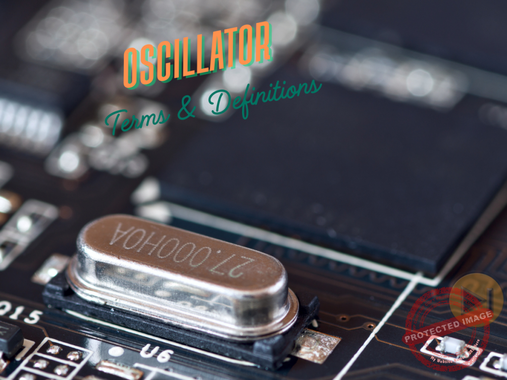
Ask any engineering student about their board exam nightmares, and oscillators will likely top the list. These complex circuits—fundamental to everything from radio communications to digital clocks—combine challenging theory with intricate mathematics that can leave even the brightest students scratching their heads the night before the exam.
If you’re preparing for your ECE or EE board exams, you’ve probably experienced that sinking feeling when facing oscillator problems. The seemingly endless varieties of oscillators, each with their own principles and applications, can make mastering this topic feel impossible. You’re not alone in this struggle.
During my years teaching engineering students, I’ve witnessed firsthand how oscillator concepts become a bottleneck for exam success. Students often memorize definitions without truly understanding the differences between oscillator types, leaving them unprepared for application-based questions that frequently appear on board exams.
This comprehensive guide aims to break down the barrier between you and oscillator mastery. I have compiled over 120 essential terms organized into logical sections, focusing specifically on the concepts most likely to appear on your board exam. Each definition is carefully crafted to be clear yet technically accurate, providing you with the perfect quick-reference guide for those final days of review.
Whether you’re struggling to differentiate between a Colpitts and Hartley oscillator, or trying to understand why crystal oscillators provide superior stability, this guide has you covered. Let’s transform oscillators from your exam weakness into your strength.
Fundamentals of Oscillation
1. Oscillator: An electronic circuit that converts DC power into an AC signal of specific frequency without requiring an input signal.
2. Oscillation: The repetitive variation of a quantity between two values, typically following sinusoidal, square, or triangular patterns.
3. Sinusoidal Oscillation: Oscillation that follows a sine wave pattern, characterized by smooth transitions between maximum and minimum values.
4. Non-sinusoidal Oscillation: Oscillation patterns that don’t follow a sine wave, including square, triangular, and sawtooth waveforms.
5. Period: The time required to complete one full cycle of oscillation, measured in seconds.
6. Frequency: The number of complete oscillations per second, measured in Hertz (Hz).
7. Angular Frequency: The rate of change of angular displacement, measured in radians per second and equal to 2πf.
8. Amplitude: The maximum displacement from the equilibrium position during oscillation.
9. Phase: The position of a point in time on a waveform cycle, measured in degrees or radians.
10. Phase Shift: The difference in phase between two waveforms having the same frequency.
11. Harmonic Oscillation: Oscillation where the restoring force is proportional to displacement from the equilibrium position.
12. Damped Oscillation: Oscillation where the amplitude decreases over time due to energy losses.
13. Undamped Oscillation: Oscillation with constant amplitude that continues indefinitely in absence of resistance.
14. Forced Oscillation: Oscillation caused by periodically applied external force.
15. Resonance: The state when a system oscillates at maximum amplitude at a specific frequency.
16. Natural Frequency: The frequency at which a system naturally oscillates after being disturbed.
Oscillator Requirements and Parameters
17. Barkhausen Criterion: The condition for sustained oscillation: loop gain must be unity (1) and phase shift must be 0° or 360°.
18. Positive Feedback: Signal feedback that adds to the input, essential for sustained oscillations.
19. Loop Gain: Total gain around a closed loop, must equal 1 at the oscillation frequency.
20. Frequency Stability: The ability of an oscillator to maintain its specified frequency over time.
21. Temperature Coefficient: The rate of frequency change due to temperature variations, measured in ppm/°C.
22. Aging Rate: The systematic change in frequency with time due to internal changes in the oscillator.
23. Frequency Pulling: The change in oscillator frequency caused by load impedance variations.
24. Frequency Pushing: The change in oscillator frequency caused by supply voltage variations.
25. Frequency Drift: Undesired change in output frequency over time.
26. Phase Noise: Random fluctuations in the phase of the waveform, a key parameter for oscillator quality.
27. Jitter: Time-domain instability of a signal’s edges relative to a reference clock.
28. Duty Cycle: The ratio of pulse duration to period of a rectangular waveform, expressed as percentage.
29. Startup Time: The time required for an oscillator to reach stable oscillation after power is applied.
30. Spectral Purity: The degree to which the oscillator output contains only the fundamental frequency without harmonics.
Oscillator Circuit Components
31. Feedback Network: Circuit elements that route a portion of the output back to the input to sustain oscillation.
32. Frequency-Determining Network: Components that set the oscillator’s operating frequency.
33. Gain Stage: The active device and associated components that provide necessary amplification.
34. Tank Circuit: A Parallel LC circuit that determines resonant frequency in LC oscillators.
35. Timing Network: Components (usually RC or LC) that determine oscillation frequency.
36. Resonator: Component that exhibits resonance at specific frequencies, such as crystals or LC circuits.
37. Varactor Diode: A voltage-dependent capacitance diode used for frequency tuning.
38. Coupling Capacitor: Capacitor used to transfer AC signals between oscillator stages while blocking DC.
39. Feedback Resistor: Resistor used to control the amount of feedback in an oscillator circuit.
40. Bias Circuit: Components that establish a proper DC operating point for active devices.
41. Compensating Network: Circuit elements that maintain stability over operating conditions.
42. Buffer Amplifier: Amplifier stage that isolates the oscillator from the load to prevent frequency pulling.
LC Oscillators
43. LC Oscillator: Oscillator using inductors and capacitors to determine frequency. Characterized by higher Q factor and better frequency stability than RC oscillators, making them suitable for RF applications.
44. Armstrong Oscillator: LC oscillator using transformer coupling for feedback. Distinguished by using a tickler coil in the collector/drain circuit coupled to the tuned circuit in the base/gate, providing good isolation between oscillator components.
45. Hartley Oscillator: LC oscillator with tapped inductor for feedback network. Key differentiator is the use of two inductors in series or a single tapped inductor, with the tap connected to ground. Suitable for frequencies from 20 kHz to 30 MHz.
46. Colpitts Oscillator: LC oscillator with tapped capacitor voltage divider for feedback. Distinguished from Hartley by using a capacitive (rather than inductive) voltage divider, offering better stability at high frequencies and commonly used in the range of 1 MHz to several hundred MHz.
47. Clapp Oscillator: Modified Colpitts oscillator with an additional series capacitor in the tank circuit. This series capacitor (smaller than the voltage divider capacitors) dominates frequency determination, providing superior frequency stability compared to the standard Colpitts design.
48. Tuned-Collector Oscillator: An LC oscillator where the resonant circuit is in the collector of the transistor. Offers better isolation of the oscillator from load variations compared to tuned-base configurations.
49. Tuned-Base Oscillator: LC oscillator where the resonant circuit is in the base of the transistor. Typically used for lower power applications and provides good frequency stability but is more susceptible to loading effects than tuned-collector types.
50. Tuned-Drain Oscillator: An LC oscillator where the resonant circuit is in the drain of the FET. Utilizes the high input impedance of FETs to minimize loading of the resonant circuit, improving frequency stability compared to BJT-based oscillators.
51. Cross-Coupled LC Oscillator: Differential oscillator topology using cross-coupled transistor pair. Distinguished by its balanced design that suppresses even-harmonic distortion and provides differential outputs, making it ideal for integrated circuit implementation.
52. Vackar Oscillator: LC oscillator with excellent frequency stability through a unique feedback arrangement. Differentiates itself from other LC oscillators by using a tapped capacitor voltage divider combined with a specific inductive feedback network that maintains near-constant loop gain across a wide tuning range.
RC Oscillators
53. RC Oscillator: Oscillator using resistors and capacitors to determine frequency. Generally simpler and less expensive than LC types but with lower Q factor and frequency stability, typically used for audio and lower frequency applications below 1 MHz.
54. Phase Shift Oscillator: RC oscillator using three RC sections to provide 180° phase shift. Distinguished by its cascade of RC networks (usually 3 sections) that each provide a 60° phase shift. Simpler design than the Wien Bridge but has higher distortion and a limited frequency range.
55. Wien Bridge Oscillator: RC oscillator using Wien network for frequency selection. Features excellent sinusoidal output with very low distortion (typically <0.01%) compared to other RC oscillators, making it ideal for audio testing and musical applications. Requires amplitude stabilization for sustained oscillation.
56. Twin-T Oscillator: RC oscillator using twin-T network for frequency determination. Unique for its high-rejection notch filter configuration that creates oscillation at the notch frequency. Provides better frequency stability than a phase shift oscillator but is more complex to design.
57. Quadrature Oscillator: Oscillator producing two sinusoidal outputs with 90° phase difference. Distinguished by using two integrators in a loop with precise gain control. Particularly valuable in applications requiring in-phase and quadrature signals such as single-sideband modulation.
58. RC Ladder Oscillator: Oscillator using a cascade of RC sections to provide the required phase shift. Compared to a standard phase shift oscillator, it uses more RC sections (4 or more) to achieve better stability and lower distortion at the expense of additional components.
59. Relaxation Oscillator: Circuit that charges and discharges a capacitor to generate a non-sinusoidal output. Unlike LC and traditional RC oscillators, it produces sawtooth, triangular, or square waves rather than sinusoidal waveforms and operates in a non-linear mode.
60. Integrator-Based Oscillator: Oscillator using op-amp integrator circuits to generate waveforms. Differs from other RC oscillators by using active integration rather than passive RC networks, providing excellent waveshape control and lower output impedance.
61. Comparator Oscillator: Oscillator using a comparator and RC timing for a non-sinusoidal output. Distinguished from op-amp based oscillators by operating in a switching mode rather than a linear mode, producing sharp-edged square waves with fast transition times.
62. Bubba Oscillator: Multiple-stage RC oscillator with excellent frequency stability. Distinguished by using four op-amp stages (each providing 45° phase shift) to achieve 180° phase shift, resulting in much better stability and distortion performance than the traditional three-stage phase shift oscillator. Crystal and Ceramic Oscillators
63. Crystal Oscillator: Oscillator using a piezoelectric crystal as frequency-determining element. Provides frequency stability 100-1000 times better than LC oscillators (typical stability: 10-50 ppm) due to the high Q factor of quartz crystals (Q = 10,000-100,000).
64. Pierce Crystal Oscillator: Common crystal oscillator configuration with the crystal connected between the inverter input and output. Distinguishes itself by operating the crystal in series resonant mode and requiring fewer components than other crystal oscillators, making it the most widely used configuration in digital circuits.
65. Colpitts Crystal Oscillator: Crystal oscillator based on Colpitts topology for improved stability. Unlike the Pierce oscillator, it incorporates the crystal as an inductive element in an LC tank circuit, allowing precise frequency adjustment through external capacitors while maintaining good stability.
66. Miller Crystal Oscillator: Crystal oscillator using Miller effect to enhance crystal operation. Characterized by operating crystal at parallel resonance and using transistor miller capacitance as part of the frequency-determining network, providing excellent phase noise performance.
67. Overtone Crystal Oscillator: Oscillator designed to operate at the crystal’s overtone frequencies rather than fundamental. Unlike fundamental mode oscillators, it incorporates additional tuned circuits to suppress the fundamental frequency and encourage oscillation at the 3rd, 5th, or 7th overtone, enabling operation at VHF/UHF frequencies (>30 MHz).
68. Temperature-Compensated Crystal Oscillator (TCXO): Crystal oscillator with additional circuitry to minimize frequency variations due to temperature. Achieves 0.1-1 ppm stability over the operating temperature range compared to 10-50 ppm for standard crystal oscillators by using thermistor networks or varactors to compensate for the crystal’s temperature coefficient.
69. Oven-Controlled Crystal Oscillator (OCXO): High-stability oscillator where crystal is maintained at constant temperature in miniature oven. Provides exceptional stability of 0.001-0.01 ppm compared to TCXO’s 0.1-1 ppm by eliminating temperature variations, but requires significantly more power and warmup time.
70. Microcomputer Crystal Oscillator: A Simple crystal oscillator integrated within microprocessors and microcontrollers. Distinguished by using an inverting amplifier with high gain, designed specifically for operation with low-cost parallel resonant crystals, typically at frequencies of 1-25 MHz.
71. Ceramic Resonator Oscillator: Oscillator using ceramic resonator instead of crystal for moderate stability applications. Offers stability between LC oscillators and crystal oscillators (typical stability: 500-2000 ppm) at lower cost and with higher shock resistance than crystals, making it ideal for consumer electronics.
72. SAW Oscillator: Oscillator employing Surface Acoustic Wave device as resonant element. Unlike crystal oscillators that use bulk acoustic waves, SAW oscillators use surface waves, enabling higher frequency operation (typically 100 MHz to 3 GHz) with good phase noise characteristics.
Voltage-Controlled Oscillators and PLL Components
73. Voltage-Controlled Oscillator (VCO): Oscillator whose frequency is controlled by input voltage. Distinguished from fixed-frequency oscillators by incorporating varactor diodes or voltage-controlled reactance to achieve frequency tuning ranges of typically 10-50% around the center frequency.
74. Current-Controlled Oscillator (CCO): Oscillator whose frequency is controlled by input current. Unlike VCOs that may suffer from power supply noise coupling through the control voltage, CCOs offer better power supply rejection and more linear tuning characteristics in many applications.
75. Voltage-to-Frequency Converter (VFC): Circuit that generates a frequency proportional to the input voltage. Unlike typical VCOs optimized for tuning range and phase noise, VFCs emphasize linearity of the voltage-to-frequency transfer function (typically 0.01-0.1% linearity) for precision analog-to-digital conversion applications.
76. Phase-Locked Loop (PLL): A Feedback system that synchronizes output frequency to the reference input. Combines a VCO with phase detection and feedback to achieve the stability of a reference oscillator while providing frequency synthesis capabilities.
77. Phase Detector: Circuit that compares the phases of two signals in PLL systems. Digital types (XOR, JK flip-flop) provide a limited phase range (0-180°) while more sophisticated types (phase-frequency detectors) offer 360° detection range with frequency discrimination capability.
78. Charge Pump: Circuit in PLL that converts phase error to control voltage. Unlike op-amp based loop filters, charge pumps provide both sourcing and sinking current capability with low offset, enabling wide loop bandwidth and fast lock times.
79. Loop Filter: Filter in PLL that removes high-frequency components from phase detector output. Order of the filter (typically 2nd or 3rd) determines loop stability, with higher-order filters providing better reference spur rejection at the expense of phase margin.
80. Frequency Divider: Circuit that reduces frequency by integer factor in frequency synthesis. Implements division ratios from 2 to several million using digital counters, enabling generation of multiple related frequencies from a single reference.
81. Frequency Synthesizer: System using PLL to generate precise frequencies from reference oscillator. Integer-N types offer simplicity but limited channel spacing, while fractional-N designs provide fine frequency resolution at the expense of increased spurious content.
82. Direct Digital Synthesizer (DDS): Digital implementation of oscillator using lookup tables and DAC. Unlike analog oscillators, provides microhertz frequency resolution with sub-microsecond switching time, though typically limited to frequencies below 1 GHz due to DAC limitations.
83. Numerically Controlled Oscillator (NCO): A Digital oscillator where frequency is determined by digital word. Similar to DDS but typically refers to the all-digital implementation without a DAC, used within digital signal processing systems rather than as standalone signal generators.
Special Oscillator Types
84. Function Generator: Device that produces various waveforms at different frequencies. Unlike single-waveform oscillators, it generates multiple waveshapes (sine, square, triangle, etc.) with amplitude, frequency, and offset control, typically covering 0.01 Hz to 20 MHz.
85. Blocking Oscillator: Oscillator that produces short pulses separated by longer intervals. Distinguished by using transformer feedback with core saturation to create a self-quenching operation, generating narrow pulses with a controlled repetition rate.
86. Multivibrator: A Circuit that generates square waves or rectangular pulses. Unlike sinusoidal oscillators, operates in switching mode between two states with active devices operating in saturation and cutoff regions.
87. Astable Multivibrator: Free-running oscillator that continuously switches between two states. Unlike monostable types, it requires no external trigger and provides a square wave output with a duty cycle determined by RC time constants.
88. Monostable Multivibrator (One-Shot): Circuit that generates single pulse when triggered. Unlike astable types, it has one stable state and requires external triggering to produce a single output pulse of predetermined duration.
89. Bistable Multivibrator (Flip-Flop): Circuit with two stable states that requires external trigger to switch states. Unlike astable and monostable types, it maintains its state indefinitely until triggered, forming the basis for digital memory elements.
90. Ring Oscillator: Chain of an odd number of inverters with output fed back to input. Distinguished by its simplicity (requiring only digital inverters) and ability to be implemented in digital CMOS with no analog components, though with relatively poor frequency stability.
91. YIG Oscillator: Oscillator using Yttrium-Iron-Garnet sphere as tunable element. Unlike varactor-tuned oscillators, offers extremely wide tuning range (typically octave bandwidth) with nearly linear tuning characteristic and excellent spectral purity at microwave frequencies.
92. Gunn Oscillator: A Microwave oscillator using a Gunn diode for negative resistance. Unlike lower frequency oscillators, it operates based on the electron transfer effect rather than PN junction characteristics, generating frequencies from 10 GHz to over 100 GHz with moderate power output.
93. Dielectric Resonator Oscillator (DRO): A Microwave oscillator using a dielectric resonator. Combines high Q factor (1000-10000) with small size compared to cavity resonators, providing excellent phase noise and stability for applications from 2 GHz to 40 GHz.
94. Magnetron Oscillator: A Microwave vacuum tube oscillator used in radar and microwave ovens. Unlike solid-state oscillators, it combines high power capability (kilowatts to megawatts) with high efficiency (~70%) using crossed electric and magnetic fields to generate microwave energy.
95. Klystron Oscillator: Vacuum tube oscillator for amplifying or generating microwaves. Distinguished from magnetrons by using velocity modulation of an electron beam through resonant cavities, providing higher frequency stability and narrower bandwidth.
96. Gyrotron Oscillator: High-power microwave oscillator using electron cyclotron resonance. Unlike conventional microwave tubes, it operates at millimeter and sub-millimeter wavelengths (30 GHz to 300 GHz) with extremely high power output (megawatts), used primarily in fusion research and advanced radar systems.
Oscillator Applications and Measurements
97. Clock Generator: Oscillator providing timing signals for digital systems.
98. Local Oscillator: Oscillator used in radio receivers for frequency conversion.
99. Beat Frequency Oscillator (BFO): Oscillator used in radio receivers to make CW signals audible.
100. Carrier Wave Generator: Oscillator producing carrier frequency for modulation in transmitters.
101. Heterodyne System: A System using oscillators to shift frequency through mixing.
102. Frequency Multiplier: A Circuit that generates output at multiple of the input frequency.
103. Frequency Mixer: A Circuit that combines two frequencies to produce sum and difference frequencies.
104. Signal Generator: Test equipment providing a calibrated oscillator output.
105. Frequency Counter: An Instrument that measures oscillator frequency.
106. Spectrum Analyzer: An Instrument that displays oscillator output in the frequency domain.
107. Oscilloscope: An Instrument that displays the oscillator output in the time domain.
108. Frequency Offset: Deviation from the specified nominal output frequency.
109. Frequency Setting Resolution: Smallest frequency change possible in an adjustable oscillator.
110. Calibration Reference: Standard oscillator used as a frequency reference for calibration.
111. Frequency Reference Standard: High-precision oscillator used as a reference for other oscillators.
112. Time Base: Precision oscillator providing a timing reference in measurement instruments.
Comparative Characteristics of Major Oscillator Families
113. LC vs. RC Oscillators: LC oscillators provide higher Q factor (typically 50-100 vs. 10-50 for RC), better frequency stability, and operation at higher frequencies (100 kHz to GHz vs. 0.1 Hz to 1 MHz for RC), but RC oscillators offer lower cost, smaller size, and eliminate inductors that are difficult to integrate.
114. Crystal vs. LC Oscillators: Crystal oscillators offer 100-1000 times better frequency stability (10-50 ppm vs. 500-10,000 ppm for LC), higher Q factor (10,000-100,000 vs. 50-100 for LC), but have limited tuning range (<0.1% vs. 10-50% for LC) and are restricted to specific frequencies determined by crystal cuts.
115. Ceramic vs. Crystal Resonators: Ceramic resonators provide moderate stability (500-2500 ppm vs. 10-50 ppm for crystals), higher shock resistance, lower cost, and faster startup time, but with inferior aging characteristics and temperature stability compared to crystals.
116. Colpitts vs. Hartley Oscillators: Colpitts oscillators use a capacitive voltage divider (better at high frequencies with lower parasitic effects) while Hartley uses an inductive divider (simpler for low frequencies). Colpitts provides better stability at high frequencies, while Hartley offers easier tuning with a single variable capacitor.
117. VCO vs. Crystal Oscillator: VCOs offer a wide frequency tuning range (typically 10-50% vs. <0.1% for crystals) and fast tuning response (microseconds vs. milliseconds for VCXO), but with significantly poorer frequency stability (500-10,000 ppm vs. 10-50 ppm) and phase noise performance.
118. DDS vs. PLL Synthesizers: DDS provides microhertz resolution and sub-microsecond switching time compared to PLL’s kilohertz resolution and millisecond switching, but PLL offers superior spectral purity at high frequencies and can exceed the Nyquist frequency limitation of DDS.
119. TCXO vs. OCXO Performance: TCXOs provide moderate stability (0.1-1 ppm) with low power consumption (milliwatts) and instant startup, while OCXOs offer superior stability (0.001-0.01 ppm) at the expense of higher power consumption (1-3 watts) and significant warmup time (minutes).
120. Blocking Oscillator vs. Multivibrator: Blocking oscillators use transformer feedback with core saturation to generate very narrow pulses with fast rise times, while multivibrators use RC timing to generate square waves with variable duty cycle control.
Mastering oscillator terminology represents a significant milestone in your engineering exam preparation journey. The 120+ terms I have covered here form the backbone of oscillator theory and applications that board examiners consistently test year after year.
Remember that success on oscillator questions depends not just on memorization, but on understanding the key differences between oscillator types. When reviewing these terms, focus particularly on:
- The defining characteristics that distinguish one oscillator from another
- The specific components that determine frequency in each oscillator type
- The stability, frequency range, and application advantages of different oscillators
- The parameters that affect oscillator performance in real-world circuits
Many students have told me that oscillator questions became their strongest section after developing a systematic approach to the terminology. Keep this guide handy during your final review sessions, and consider creating flashcards for the terms you find most challenging.
For practice, try describing each oscillator type without looking at the definition, focusing on what makes it unique compared to similar oscillators. This comparative approach mirrors how board exams often frame their questions.
As your exam approaches, remember that confidence comes from preparation. The hours you invest now in mastering these terms will pay dividends not just during your board exam, but throughout your engineering career when you encounter these circuits in practical applications.
Best of luck on your upcoming exams! With this guide as your companion, you’re well-equipped to tackle any oscillator question that comes your way.
Related Content

P inoyBIX educates thousands of reviewers and students a day in preparation for their board examinations. Also provides professionals with materials for their lectures and practice exams. Help me go forward with the same spirit.
“Will you subscribe today via YOUTUBE?”
TIRED OF ADS?
- Become Premium Member and experienced complete ads-free content browsing.
- Full Content Access to Premium Solutions Exclusive for Premium members
- Access to PINOYBIX FREEBIES folder
- Download Reviewers and Learning Materials Free
- Download Content: You can see download/print button at the bottom of each post.
PINOYBIX FREEBIES FOR PREMIUM MEMBERSHIP:
- CIVIL ENGINEERING REVIEWER
- CIVIL SERVICE EXAM REVIEWER
- CRIMINOLOGY REVIEWER
- ELECTRONICS ENGINEERING REVIEWER (ECE/ECT)
- ELECTRICAL ENGINEERING & RME REVIEWER
- FIRE OFFICER EXAMINATION REVIEWER
- LET REVIEWER
- MASTER PLUMBER REVIEWER
- MECHANICAL ENGINEERING REVIEWER
- NAPOLCOM REVIEWER
- Additional upload reviewers and learning materials are also FREE
FOR A LIMITED TIME
If you subscribe for PREMIUM today!
You will receive an additional 1 month of Premium Membership FREE.
For Bronze Membership an additional 2 months of Premium Membership FREE.
For Silver Membership an additional 3 months of Premium Membership FREE.
For Gold Membership an additional 5 months of Premium Membership FREE.
Join the PinoyBIX community.