

This is the Multiples Choice Questions Part 18 of the Series in Electrical Circuit as one of the Electronics Engineering topic. In Preparation for the ECE Board Exam make sure to expose yourself and familiarize in each and every questions compiled here taken from various sources including but not limited to past Board Exam Questions in Electronics Engineering field, Electronics Books, Journals and other Electronics References.
MCQ Topic Outline included in ECE Board Exam Syllabi
- MCQ in AC-DC circuits
- MCQ in Resistors
- MCQ in Inductors
- MCQ in Capacitors
Continue Practice Exam Test Questions Part 18 of the Series
Choose the letter of the best answer in each questions.
851. The value of Rth in Fig. 17.9(b) is _________.
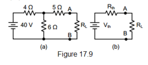
electrical circuit figure 17.9
A. 15 Ω
B. 3.5 Ω
C. 6.4 Ω
D. 7.4 Ω
Answer: Option D
Solution:
852. The open-circuited voltage at terminals AB in Fig. 17.9(a) is
electrical circuit figure 17.9
A. 12 V
B. 20 V
C. 24 V
D. 40 V
Answer: Option C
Solution:
853. For transfer of maximum power in the circuit shown in Fig. 17.9(a), the value of RL should be _________.
electrical circuit figure 17.9
A. 3.5 Ω
B. 6.4 Ω
C. 7.4 Ω
D. 15 Ω
Answer: Option C
Solution:
854. Fig. 18.2(b) shows Norton’s equivalent circuit of Fig. 3.5(a). The value of RN is _______.
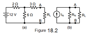
electrical circuit figure 18.2
A. 5 Ω
B. 4.5 Ω
C. 10.5 Ω
D. none of the above
Answer: Option B
Solution:
855. The value of IN in Fig. 8.2(b) is _________.
electrical circuit figure 18.2
A. 3 A
B. 1 A
C. 2 A
D. none of the above
Answer: Option C
Solution:
856. Thevenin’s theorem is _________ form on an equivalent circuit.
A. voltage
B. current
C. both voltage and current
D. none of the above
Answer: Option A
Solution:
857. Norton’s theorem is ________ Thevenin’s theorem.
A. A the same as.
B. converse of
C. equal to
D. none of the above
Answer: Option B
Solution:
858. In the analysis of a vacuum tube circuit, we generally use _________.
A. superposition
B. Norton’s
C. Thevenin’s
D. reciprocity
Answer: Option C
Solution:
859. Norton’s theorem is __________ form of an equivalent circuit
A. voltage
B. current
C. both voltage and current
D. none of the above
Answer: Option B
Solution:
860. In the analysis of a transistor circuit, we generally use _________.
A. Norton’s
B. Thevenin’s
C. reciprocity
D. superposition
Answer: Option A
Solution:
861. Fig. 18.3(a) shows Norton’s equivalent circuit of a network whereas Fig. 18.3(b) shows its Thevenin’s equivalent circuit. The value of Vth is ________.
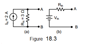
electrical circuit figure 18.3
A. 1.5 V
B. 0.866 V
C. 3 V
D. 6 V
Answer: Option D
Solution:
862. The value of Rth in Fig. 18.3(b) is ________.
electrical circuit figure 18.3
A. 3 Ω
B. 2 Ω
C. 1.5 Ω
D. 6 Ω
Answer: Option A
Solution:
863. If in Fig. 18.3(a), the value of IN is 3 A, then value of Vth in Fig. 18.3(b) will be _________.
electrical circuit figure 18.3
A. 1 V
B. 9 V
C. 5 V
D. none of these
Answer: Option B
Solution:
864. For maximum power transfer, the relation between load resistance RL and internal resistance Ri of the voltage source is _________.
A. RL = 2Ri
B. RL = 0.5Ri
C. RL = 1.5Ri
D. RL = Ri
Answer: Option D
Solution:
865. Under the conditions of maximum power transfer, the efficiency is _________.
A. 75%
B. 100%
C. 50%
D. 25%
Answer: Option C
Solution:
866. The open-circuited voltage at terminals of load RL is 30 V Under the conditions of maximum power transfer, the load voltage would be _________.
A. 30 V
B. 10 V
C. 5 V
D. 15 V
Answer: Option D
Solution:
867. The maximum power transfer theorem is used in _________.
A. electronic circuits
B. power system
C. home lighting circuits
D. none of these
Answer: Option A
Solution:
868. Under the conditions of maximum power transfer, a voltage source is delivering a power of 30 W to the load. The power generated by the source is __________.
A. 45 W
B. 30 W
C. 60 W
D. 90 W
Answer: Option C
Solution:
869. For the circuit shown in Fig. 18.4, the power transferred will be maximum when RL is equal to _______.
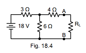
electrical circuit figure 18.4
A. 4.5 Ω
B. 6 Ω
C. 3 Ω
D. none of these
Answer: Option B
Solution:
870. The open-circuited voltage at terminals AB in Fig. 18.4 is _________.
electrical circuit figure 18.4
A. 12 V
B. 6 V
C. 15 V
D. 9.5 V
Answer: Option A
Solution:
871. If in Fig. 18.4, the value of RL = 6 Ω, then current through RL is _______.
electrical circuit figure 18.4
A. 2 A
B. 1.5 A
C. 1.75 A
D. 1 A
Answer: Option D
Solution:
872. Under the conditions of maximum power transfer, the voltage across RL in Fig. 18.4 is _________.
electrical circuit figure 18.4
A. 6 V
B. 4 V
C. 9 V
D. 12 V
Answer: Option A
Solution:
873. The output resistance of a voltage source is 4 Ω. Its internal resistance will be ________.
A. 4 Ω
B. 2 Ω
C. 1 Ω
D. infinite
Answer: Option A
Solution:
874. Delta/star of star/delta transformation technique is applied to _________.
A. one terminal
B. two terminal
C. three terminal
D. none of the above
Answer: Option C
Solution:
875. Kirchhoff’s current law is applicable to only
A. closed loops in a network
B. electronic circuits
C. conjunctions in a network
D. electric circuits
Answer: Option C
Solution:
876. Kirchhoff’s voltage law is concerned with
A. IR drops
B. battery e.m.f.s.
C. junction voltages
D. both A and B
Answer: Option D
Solution:
877. According to KVL, the algebraic sum of all IR drops and e.m.f.s in any closed loop of a network is always
A. zero
B. positive
C. negative
D. determined by the battery e.m.f.s
Answer: Option A
Solution:
878. The algebraic sign of an IR drop is primarily dependent upon the
A. amount of current flowing through it
B. value of R
C. direction of current flow
D. battery connection
Answer: Option C
Solution:
879. Maxwell’s loop current method of solving electrical networks
A. uses branch currents
B. utilizes Kirchhoff’s voltage law
C. is confined to single-loop circuits
D. is a network reduction method
Answer: Option B
Solution:
880. Point out the WRONG statement. In the node-voltage technique of solving networks, choice of a reference node does not
A. affect the operation of the circuit
B. change the voltage across any element
C. alter the p.d. between any pair of nodes
D. affect the voltages of various nodes
Answer: Option D
Solution:
881. The nodal analysis is primarily based on the application of
A. KVL
B. KCL
C. Ohm’s Law
D. both B and C
Answer: Option D
Solution:
882. Superposition theorem is can be applied only to circuits having _________ elements.
A. non-linear
B. passive
C. linear bilateral
D. resistive
Answer: Option C
Solution:
883. The Superposition theorem is essentially based on the concept of
A. duality
B. linearity
C. reciprocity
D. non-linearity
Answer: Option C
Solution:
884. While Thevenizing a circuit between two terminals, Vth equals
A. short-circuit terminal voltage
B. open circuit terminal voltage
C. EMF of the battery nearest to the terminal
D. net voltage available in the circuit
Answer: Option B
Solution:
885. Thevenin resistance Rth is found
A. between any two “open” terminals
B. by short-circuiting the given two terminals
C. by removing voltage sources along with their internal resistance
D. between same open terminals as for Vth
Answer: Option D
Solution:
886. While calculating Rth, constant -current sources in the circuit are
A. replaced by “opens”
B. replaced by “shorts”
C. treated in parallel with other voltage sources
D. converted into equivalent voltage sources
Answer: Option A
Solution:
887. Thevenin resistance of the circuit of Fig. 18.5 across its terminals A and B is ______ ohm.
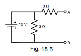
electrical circuit figure 18.5
A. 6 ohms
B. 3 ohms
C. 9 ohms
D. 2 ohms
Answer: Option A
Solution:
888. The load resistance needed to extract maximum power from the circuit of Fig. 18.6 is _______ ohm.
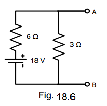
electrical circuit figure 18.6
A. 2 ohms
B. 9 ohms
C. 6 ohms
D. 18 ohms
Answer: Option C
Solution:
889. The Norton equivalent circuit for the network of Fig. 18.6 between A and B is ______ current source with parallel resistance of ______.
electrical circuit figure 18.6
A. 2 A, 6 Ω
B. 3 A, 2 Ω
C. 2 A, 3 Ω
D. 3 A, 9 Ω
Answer: Option B
Solution:
890. The Norton equivalent of a circuit consists of a 2 A current source in parallel with a 4 Ω resistor. Thevenin equivalent of this circuit is a ____ volt source in series with a 4 Ω resistor.
A. 2 ohms
B. 0.5 ohms
C. 6 ohms
D. 8 ohms
Answer: Option D
Solution:
891. If two identical 3 A, 4 Ω Norton equivalent circuits are connected in parallel with like polarity to like, the combined Norton equivalent circuit is
A. 6 A, 4 Ω
B. 6 A, 2 Ω
C. 3 A, 2 Ω
D. 6 A, 8 Ω
Answer: Option D
Solution:
892. Two 6 V, 2 Ω batteries are connected in series aiding. This combination can be replaced by a single equivalent current generator of ______ with a parallel resistance of ______ ohm.
A. 3 A, 4 Ω
B. 3 A, 2 Ω
C. 3 A, 1 Ω
D. 5 A, 2 Ω
Answer: Option B
Solution:
893. Two identical 3 A, 1 Ω batteries are connected in parallel with like polarity with like polarity to like. The Norton equivalent circuit of the combination is
A. 3 A, 0.5 Ω
B. 6 A, 1 Ω
C. 3 A, 1 Ω
D. 6 A, 0.5 Ω
Answer: Option D
Solution:
894. Thevenin equivalent circuit of the network shown in Fig. 18.7 is required. The value of the open-circuit voltage across terminals A and B of this circuit is ________ volt.
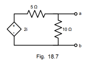
electrical circuit figure 18.7
A. zero
B. 2i/10
C. 2i/5
D. 2i
Answer: Option A
Solution:
895. For a linear network containing generators and impedance, the ratio of the voltage to the current produced in other loop is the same as the ratio of voltage and current obtained when the positions of the voltage source and the ammeter measuring the current are interchanged. This network theorem is known as _________ theorem.
A. Millman’s
B. Norton’s
C. Tellegen’s
D. Reciprocity
Answer: Option D
Solution:
896. A 12 volt source with an internal resistance of 1.2 ohms is connected across a wire-wound resistor. Maximum power will be dissipated in the resistor when its resistance is equal to
A. zero
B. 1.2 ohm
C. 12 ohms
D. infinity
Answer: Option B
Solution:
897. Three 3.33 Ω resistors are connected in wye. What is the value of the equivalent resistors connected in delta?
A. 3.33 Ω
B. 10 Ω
C. 6.67 Ω
D. 20 Ω
Answer: Option B
Solution:
898. Find the equivalent resistance between terminals a and b of the circuit shown. Each resistance has a value of 1 ohm.
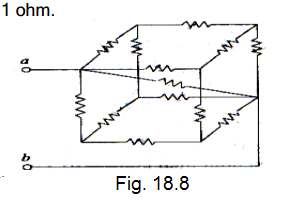
electrical circuit figure 18.8
A. 5/6 ohms
B. 5/11 ohms
C. 5/14 ohms
D. 5/21 ohms
Answer: Option B
Solution:
899. What do you call the head to tail connection of two or more op-amp circuits wherein the output of one op-amp is the input of another op-amp?
A. Parallel Op-Amps
B. Follow-Thru Connection
C. Cascade Connection
D. Series Op-Amps
Answer: Option C
Solution:
900. Find the power dissipation in the 6 ohms resistor in the next figure.
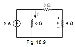
electrical circuit figure 18.9
A. 54 W
B. 216 W
C. 121.5 W
D. 150 W
Answer: Option B
Solution:
Questions and Answers in Electrical Circuit
Following is the list of practice exam test questions in this brand new series:
Complete List of MCQ in Electronics Engineering per topic
Related Content


P inoyBIX educates thousands of reviewers and students a day in preparation for their board examinations. Also provides professionals with materials for their lectures and practice exams. Help me go forward with the same spirit.
“Will you subscribe today via YOUTUBE?”
TIRED OF ADS?
- Become Premium Member and experienced complete ads-free content browsing.
- Full Content Access to Premium Solutions Exclusive for Premium members
- Access to PINOYBIX FREEBIES folder
- Download Reviewers and Learning Materials Free
- Download Content: You can see download/print button at the bottom of each post.
PINOYBIX FREEBIES FOR PREMIUM MEMBERSHIP:
- CIVIL ENGINEERING REVIEWER
- CIVIL SERVICE EXAM REVIEWER
- CRIMINOLOGY REVIEWER
- ELECTRONICS ENGINEERING REVIEWER (ECE/ECT)
- ELECTRICAL ENGINEERING & RME REVIEWER
- FIRE OFFICER EXAMINATION REVIEWER
- LET REVIEWER
- MASTER PLUMBER REVIEWER
- MECHANICAL ENGINEERING REVIEWER
- NAPOLCOM REVIEWER
- Additional upload reviewers and learning materials are also FREE
FOR A LIMITED TIME
If you subscribe for PREMIUM today!
You will receive an additional 1 month of Premium Membership FREE.
For Bronze Membership an additional 2 months of Premium Membership FREE.
For Silver Membership an additional 3 months of Premium Membership FREE.
For Gold Membership an additional 5 months of Premium Membership FREE.
Join the PinoyBIX community.