
This is the Multiple Choice Questions Part 7 of the Series in AC Circuits as one of the Electrical Engineering topic. In Preparation for the REE Board Exam make sure to expose yourself and familiarize in each and every questions compiled here taken from various sources including but not limited to past Board Exam Questions in Electrical Engineering field, Electrical Engineering Books, Journals and other Electrical Engineering References.
Continue Practice Exam Test Questions Part 7 of the Series
SERIES CIRCUITS
Choose the letter of the best answer in each questions.
⇐ MCQ in AC Circuits Part 6 | REE Board Exam
301. A circuit component that opposes the change in circuit voltage is
A. resistance
B. capacitance
C. inductance
D. all of these
Answer: Option B
Solution:
302. Power loss in an electrical circuit can take place in
A. inductance only
B. capacitance only
C. inductance and resistance
D. resistance only
Answer: Option D
Solution:
303. A circuit of zero lagging power factor behaves as
A. an inductive circuit
B. a capacitive circuit
C. R-L circuit
D. R-C circuit
Answer: Option A
Solution:
304. In an R-L series circuit the power factor is
A. leading
B. lagging
C. zero
D. unity
Answer: Option B
Solution:
305. When a sinusoidal voltage is applied across an R-L series circuit having R = XL, the phase angle will be
A. 90°
B. 45° lagging
C. 45° leading
D. 90° leading
Answer: Option B
Solution:
306. An ac source having voltage e = 110 sin (ωt + π/3) is connected in an ac circuit. If the current drawn from the circuit varies as i = 5 sin (ωt – π/3) the impedance of the circuit will be
A. 22 Ω
B. 16 Ω
C. 30.8 Ω
D. none of these
Answer: Option A
Solution:
307. Which are of the following true of the circuit shown in the given figure?
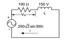
1. VR = 100√2 V 2. I = 2 A 3. L = 0.25 H
Select the correct answer using the codes given below:
Codes:
A. 2 and 3
B. 1 and 2
C. 1 and 3
D. 1, 2 and 3
Answer: Option A
Solution:
308. The R-L circuit of the figure is fed from a constant magnitude variable frequency sinusoidal voltage source vin. At 100 Hz, the R and L element each has a voltage drop Vrms. If the frequency of the source is changes to 50 Hz, then new voltage drop across R is
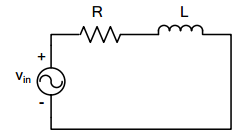
A. √(5/8) Vrms
B. √(2/3) Vrms
C. √(8/5) Vrms
D. √(3/2) Vrms
Answer: Option C
Solution:
309. An ac source of 200 Vrms supplies active power of 600 W and reactive power of 800 VAR. The rms current drawn from the source is
A. 10 A
B. 5 A
C. 3.75 A
D. 2.5 A
310. A square wave is fed to an R-C circuit. Then
A. voltage across R is square and across C is not square
B. voltage across C is square and across R is not square
C. voltage across both R and C is square
D. voltage across both R and C is not square
Answer: Option D
Solution:
311. The voltage phasor of a circuit is 10∠15° V and the current phasor is 2∠-45° A. The active and reactive powers in the circuit are
A. 10 W and 17.32 VAR
B. 5 W and 8.66 VAR
C. 20 W and 60 VAR
D. 20√2 W and 10√2 VAR
Answer: Option A
Solution:
312. In a two-element series circuit, the applied voltage and resultant current are respectively, v(t) = 50 + 50 sin (5 x 10³ t) and i(t) = 11.2 sin (5 x 10³ t + 63.4°). The nature of the elements would be
A. R-L
B. R-C
C. L-C
D. neither R, nor L, nor C
Answer: Option B
Solution:
313. A series circuit passive elements has the following current and applied voltage: v = 200 sin (2,000t + 50°), i = 4 cos (2,000t + 13.2°). The circuit elements
A. must be resistance and capacitance
B. must be resistance and inductance
C. must be inductance, capacitance and resistance
D. could be either resistance and capacitance or resistance, inductance and capacitance
Answer: Option D
Solution:
314. A two terminal black box contains one of the R-L-C elements. The black box is connected to a 220 V ac supply. The current through the source is I. When a capacitance of 0.1 F is inserted in series between the source and the box, the current through the source is 2I. The element is
A. a resistance
B. an inductance
C. a capacitance
D. it is not possible to determine the element
Answer: Option B
Solution:
315. In the following circuit, i(t) under steady state is
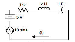
A. zero
B. 5
C. 7.07 sin t
D. 7.07 sin (t – 45°)
Answer: Option D
Solution:
316. The source in the circuit is a sinusoidal source. The supply voltages across various elements are marked in the figure. The input voltage is
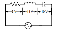
A. 10 V
B. 5 V
C. 27 V
D. 24 V
Answer: Option B
Solution:
317. In the circuit shown in the given figure, if the power consumed by the 5 Ω resistor is 10 W, then the pf of the circuit is
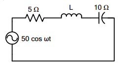
A. 0.8
B. 0.6
C. 0.5
D. zero
Answer: Option B
Solution:
318. In an RL circuit, supplied from an ac source, the reactive power is proportional to the
A. the average energy stored in the electric field
B. the average energy stored in the magnetic field
C. sum of the average energy stored in the electric field and that stored in the magnetic field
D. difference of the average energy stored in the electric field and that stored in the magnetic field
Answer: Option D
Solution:
319. If a series RLC circuit excited by a voltage e = E sin ωt when LC < 1/ω2
A. current lags behind the applied voltage
B. current leads the applied voltage
C. current is in phase with the applied voltage
D. voltage across L and C are equal
Answer: Option B
Solution:
320. The current in the circuit shown is
A. 5 A
B. 10 A
C. 15 A
D. 25 A
Answer: Option A
Solution:
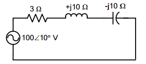
321. In the case of the R-L-C circuit shown in the given figure, the voltage across the R, L and C would be respectively
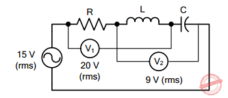
A. 12 V, 16 V and 7 V or 25 V
B. 16 V, 12 V and 7 V or 25 V
C. 7 V, 16 V and 12 V
D. 16 V, 12 V and 25 V
Answer: Option A
Solution:
322. Consider the following statements regarding the circuit shown in the figure.
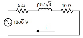
If the power consumed by 5 Ω resistor is 10 W then
1. |I| = √2 A
2. the total impedance of the circuit is 5 Ω
3. cos θ = 0.866
Which of these statements is correct?
A. 1 and 3
B. 2 and 3
C. 1 and 2
D. 1, 2 and 3
Answer: Option A
Solution:
323. In an ac circuit if voltage V = (a + jb) and current I = (c + jd), then the power is given by
A. ac + ad
B. ac + bd
C. bc – ad
D. bc + ad
Answer: Option B
Solution:
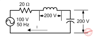
324. The reactive power drawn from the source in the network in the given figure is
A. 300 VAR
B. 200 VAR
C. 100 VAR
D. zero
Answer: Option D
Solution:
325. A series R-L-C circuit, consisting of R = 10 Ω, XL = 20 Ω, XC = 20 Ω is connected across an ac supply of 100 V (rms). The magnitude and phase angle (with reference to supply voltage) of the voltage across the inductive coil are respectively
A. 100 V, 90°
B. 100 V, -90°
C. 200 V, -90°
D. 200 V, 90°
Answer: Option D
Solution:
326. For a capacitor in a sine wave ac circuit
A. vC lags iC by 90°
B. iC leads vC by 90°
C. iC and vC have the same frequency
D. all of these
Answer: Option D
Solution:
327. In a series RC circuit,
A. VC leads VR by 90°
B. VC and I are in phase
C. VC lags VR by 90°
D. both B and C
Answer: Option C
Solution:
328. In a series RC circuit,
A. VC and VR are in phase
B. VT and I are always in phase
C. VR and I are in phase
D. VR leads I by 90°
Answer: Option C
Solution:
329. When the frequency of the applied voltage increases in a series RC circuit
A. the phase angle, θT, becomes more negative
B. ZT increases
C. ZT decreases
D. both A and B
Answer: Option C
Solution:
330. Inductive reactance, XL
A. applies only to non-sinusoidal waveforms or dc
B. applies only to sine waves
C. applies to either sinusoidal or non-sinusoidal waveforms
D. is inversely proportional to frequency
Answer: Option B
Solution:
331. For an inductor in a sine wave ac circuit
A. VT leads iL by 90°
B. VT lags iL by 90°
C. VT and iL are in phase
D. none of these
Answer: Option A
Solution:
332. In a series RL circuit,
A. VT lags VR by 90°
B. VT leads VR by 90°
C. VR and I are in phase
D. both B and C
Answer: Option D
Solution:
333. In a series RL circuit where XL = R, the phase angle, θZ, is
A. -45°
B. 0°
C. 90°
D. 45°
Answer: Option D
Solution:
In a series RL circuit where the inductive reactance (XL) is equal to the resistance (R), it implies that the phase angle between the voltage and the current is 45 degrees, as the impedance (Z) is purely resistive. Therefore, the correct answer is:
D. 45°
334. In an ac circuit with only series resistances
A. VT and I are in phase
B. RT =R1 + R2 + R3 + … + etc.
C. each voltage drop is in phase with the series current
D. all of these
Answer: Option D
Solution:
335. The unit of apparent power is the
A. volt-ampere (VA)
B. watt (W)
C. volt-ampere-reactive (VAR)
D. joule (J)
Answer: Option A
Solution:
336. In an ac circuit with only series capacitors
A. VT leads I by 90°
B. VT lags I by 90°
C. each capacitor voltage drop leads I by 90°
D. both A and C
Answer: Option B
Solution:
337. The unit of real power is the
A. watt (W)
B. volt-ampere (VA)
C. joule (J)
D. volt-ampere-reactive (VAR)
Answer: Option A
Solution:
338. In a series RLC circuit
A. XL and XC are 180° out of phase
B. IL and IC are 180° out of phase
C. XL and XC are 90° out of phase
D. XL and XC are in phase
Answer: Option A
Solution:
339. The power factor of an ordinary electric bulb is
A. zero
B. unity
C. slightly more than unity
D. slightly less than unity
Answer: Option B
Solution:
340. The power factor of an ac circuit is equal to
A. cosine of the phase angle
B. sine of the phase angle
C. unity for a resistive circuit
D. unity for a reactive circuit
Answer: Option A
Solution:
341. If f(t) = sin t + sin √2 t is passing through R = 1 ohm, what is the power dissipated in 1 ohm resistor?
A. 1 W
B. 2 W
C. since f(t) in non-periodic, not possible to find power
D. none of these
Answer: Option A
Solution:
C. PARALLEL CIRCUITS
342. EE Board Exam October 1981
A circuit consists of XL = j5 ohms, XC = -j5 ohms and R = 5 ohms all are connected in parallel. Find the equivalent impedance.
A. 5.5 Ω
B. 5.0 Ω
C. 4.8 Ω
D. 5.2 Ω
343. EE Board Exam October 1985
Given: Z1 = -j2.5 ohms; Z2 = j4 ohms; Z3 = 5 ohms; Z4 = 1 + j5 ohms. If the four impedances are connected in parallel, find the equivalent impedance in ohms.
A. 4.1 + j0.72
B. 4.3 + j0.45
C. 4.2 + j0.35
D. 4.0 + j0.97
Answer: Option A
Solution:
344. EE Board Exam April 1984, April 1987
Three impedances Za = 3 + j4 ohms, Zb = 4 – j4 ohms and Zc = j3 ohms are connected in parallel. Solve for the pf of the combination.
A. 0.653 leading
B. 0.554 lagging
C. 0.503 leading
D. 0.620 lagging
Answer: Option B
Solution:
345. EE Board Exam October 1993
A pure capacitance of 530.515 x 10⁻⁶ farad and an inductance of 530.515 x 10⁻⁴ Henry are connected in parallel across an ac power source. Solve for the resultant impedance assuming that the frequency is 30 Hz.
A. 10 Ω
B. infinite
C. zero
D. undefined
Answer: Option B
Solution:
346. REE Board Exam March 1998
A coil of a 50-ohm resistance and of 150 mH inductance is connected in parallel with a 50 μF capacitor. What is the power factor of the circuit?
A. 80%
B. 50%
C. 70%
D. 60%
347. EE Board Exam April 1982
Three impedances Za, Zb and Zc are connected in parallel. If at 60 Hz, Za = j8, Zb = -j2 and Zc = 5 ohms. Solve for the resultant power factor.
A. 0.471 lagging
B. 0.471 leading
C. 0.573 lagging
D. 0.573 leading
Answer: Option B
Solution:
348. REE Board Exam October 1997
A resistor of 50 ohms and an impedance of 100 + j50 ohms are connected in parallel across a 220 volts supply. What is the power factor of the load?
A. 96%
B. 99%
C. 98%
D. 95%
349. EE Board Exam October 1992
A capacitor of 3.18 microfarads is connected in parallel with a resistance of 2,000 ohms. The combination is further connected in series with an inductance of 795 mH and resistance of 100 ohms across a supply given by e = 400 sin wt + 80 sin (3wt + 60°). Assume w = 314 radians/sec. Determine the power dissipated.
A. 74.66 W
B. 78.05 W
C. 80.28 W
D. 75.66 W
Answer: Option A
Solution:
350. EE Board Exam October 1992
A capacitor of 3.18 microfarads is connected in parallel with a resistance of 2,000 ohms. The combination is further connected in series with an inductance of 795 mH and resistance of 100 ohms across a supply given by e = 400 sin wt + 80 sin (3wt + 60°). Assume w = 314 radians/sec. Determine the circuit power factor.
A. 0.702
B. 0.650
C. 0.633
D. 0.612
Answer: Option B
Solution:
⇒ MCQ in AC Circuits Part 8 | REE Board Exam
Questions and Answers in AC Circuits
Following is the list of practice exam test questions in this brand new series:
Related Content


P inoyBIX educates thousands of reviewers and students a day in preparation for their board examinations. Also provides professionals with materials for their lectures and practice exams. Help me go forward with the same spirit.
“Will you subscribe today via YOUTUBE?”
TIRED OF ADS?
- Become Premium Member and experienced complete ads-free content browsing.
- Full Content Access to Premium Solutions Exclusive for Premium members
- Access to PINOYBIX FREEBIES folder
- Download Reviewers and Learning Materials Free
- Download Content: You can see download/print button at the bottom of each post.
PINOYBIX FREEBIES FOR PREMIUM MEMBERSHIP:
- CIVIL ENGINEERING REVIEWER
- CIVIL SERVICE EXAM REVIEWER
- CRIMINOLOGY REVIEWER
- ELECTRONICS ENGINEERING REVIEWER (ECE/ECT)
- ELECTRICAL ENGINEERING & RME REVIEWER
- FIRE OFFICER EXAMINATION REVIEWER
- LET REVIEWER
- MASTER PLUMBER REVIEWER
- MECHANICAL ENGINEERING REVIEWER
- NAPOLCOM REVIEWER
- Additional upload reviewers and learning materials are also FREE
FOR A LIMITED TIME
If you subscribe for PREMIUM today!
You will receive an additional 1 month of Premium Membership FREE.
For Bronze Membership an additional 2 months of Premium Membership FREE.
For Silver Membership an additional 3 months of Premium Membership FREE.
For Gold Membership an additional 5 months of Premium Membership FREE.
Join the PinoyBIX community.